Method of repairing a turbine engine component

a technology of turbine engines and components, applied in the direction of machines/engines, liquid fuel engines, mechanical equipment, etc., can solve the problems of time-consuming and labor-intensive repair techniques, significant stress on parts of turbine engines, and wear of worn parts

Active Publication Date: 2009-03-12
RTX CORP
View PDF22 Cites 10 Cited by
  • Summary
  • Abstract
  • Description
  • Claims
  • Application Information

AI Technical Summary

Problems solved by technology

Parts of a turbine engine are subject to significant stress and wear.
Existing techniques for repairing worn parts are both time consuming and labor intensive.

Method used


Image

  • Method of repairing a turbine engine component
  • Method of repairing a turbine engine component
  • Method of repairing a turbine engine component

Examples


Embodiment Construction

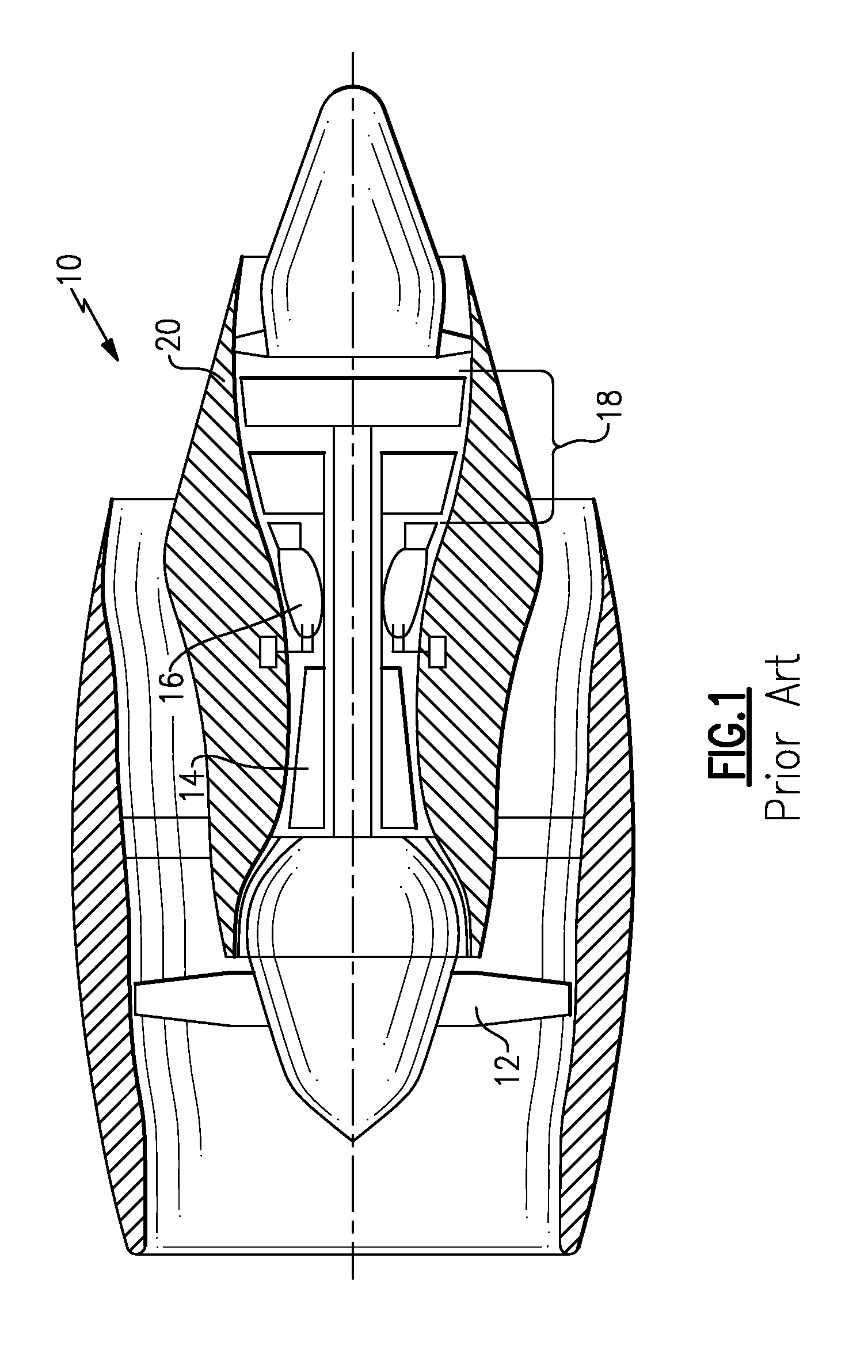
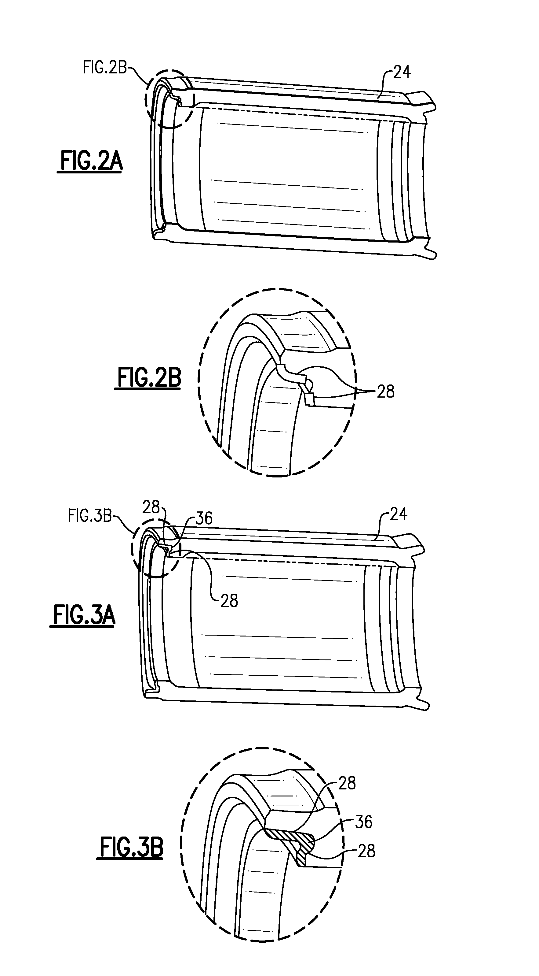
[0015]FIG. 1 illustrates an example of a turbine engine 10, here a turbofan engine, that would benefit from the inventive repair technique. As other types of turbine engines, such as a turbojet engine, will likewise benefit from the inventive technique, the term turbine engine is not limited to the disclosed embodiment. As shown, turbine engine 10 has a fan 12 or propeller through which ambient air is propelled. A multi-stage compressor 14 pressurizes the air and is in communication with a combustor 16 that mixes the compressed air with fuel. The combustor 16 ignites the fuel-air mixture. Expanded gas then passes through turbine section 18 as known. Surrounding turbine section 18 is a shroud 20, composed of shroud segments, such as shown in FIGS. 2A and 3A.

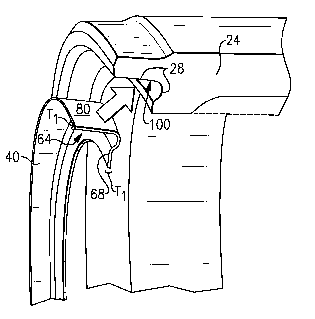
[0016]As shown in FIG. 2A and FIG. 5, turbine engine component 24, here a compressor shroud segment, may have tongue 58 and face 62 to be received by a groove (not shown) formed in shroud 20 to allow turbine engine component 24 to...


PUM

PropertyMeasurementUnit
areaaaaaaaaaaa
shapeaaaaaaaaaa
dimensionsaaaaaaaaaa

Abstract

The inventive method involves the inspection of a turbine engine. A damaged component of the turbine engine is identified. Portions of the turbine engine component are removed from the damaged area to accommodate an overlay. The overlay is sized smaller than the turbine engine component. The overlay is then placed in a location previously occupied by the removed portion and attached to the turbine engine component.

Description

BACKGROUND OF THE INVENTION[0001]This invention relates to a method of repairing a turbine engine, including parts of the engine.[0002]Parts of a turbine engine are subject to significant stress and wear. From time to time, it may become necessary to repair or replace these components. Because of their cost, repair may be preferable to the replacement of the entire component. Repair of these components may include the build-up of damaged areas to original dimensions by welding, nickel plating, plasma spraying or other restoration techniques. Further machining of these areas may be required to conform these parts to their original dimensions. Existing techniques for repairing worn parts are both time consuming and labor intensive.[0003]Accordingly, a need exists to reduce the time and labor associated with repairing the components of a turbine engine.SUMMARY OF THE INVENTION[0004]The present invention concerns a method of repairing a turbine engine. During an inspection of the turbin...

Claims


Application Information

Patent Timeline
Patent Type & Authority Applications(United States)
IPC IPC(8): B23P6/00F02C7/00
CPCB23P6/005F01D25/246Y10T29/49318Y10T29/49734F05D2230/80Y10T29/49737
Inventor REYNOLDS, GEORGE H.ADDIS, MARK E.
Owner RTX CORP
Why Eureka
Try Eureka