Fuel injection assemblies in combustion turbine engines

a technology of combustion turbine engine and fuel injection assembly, which is applied in the direction of continuous combustion chamber, combustion process, lighting and heating apparatus, etc., can solve the problems of increasing manufacturing and installation costs, high cost of conventional late lean injection assembly, and high cost of new gas turbine units and existing units

Active Publication Date: 2016-04-12
GE INFRASTRUCTURE TECH INT LLC
View PDF40 Cites 9 Cited by
  • Summary
  • Abstract
  • Description
  • Claims
  • Application Information

AI Technical Summary

Problems solved by technology

Multiple designs exist for staged combustion in combustion turbine engines, but most are complicated assemblies consisting of a plurality of tubing and interfaces.
Conventional late lean injection assemblies are expensive and costly for both new gas turbine units and retrofits of existing units.
One of the reasons for this is the complexity of conventional late lean injection systems, particularly those systems associated with the fuel and air delivery.
The many parts associated with these complex systems must be designed to withstand the extreme thermal and mechanical loads of the turbine environment, which significantly increases manufacturing and installation cost.
Even so, conventional late lean injection assemblies still have a high risk for fuel leakage into the compressor discharge casing, which can result in auto-ignition and a safety issue.
Additionally, conventional late lean injectors perform poorly in regard to providing a well-mixed fuel / air mixture for combustion within the combustion chamber.
Further, conventional designs fail to efficiently use air supplied from within the flow annulus formed of the combustor.

Method used


Image

  • Fuel injection assemblies in combustion turbine engines
  • Fuel injection assemblies in combustion turbine engines
  • Fuel injection assemblies in combustion turbine engines

Examples


Embodiment Construction

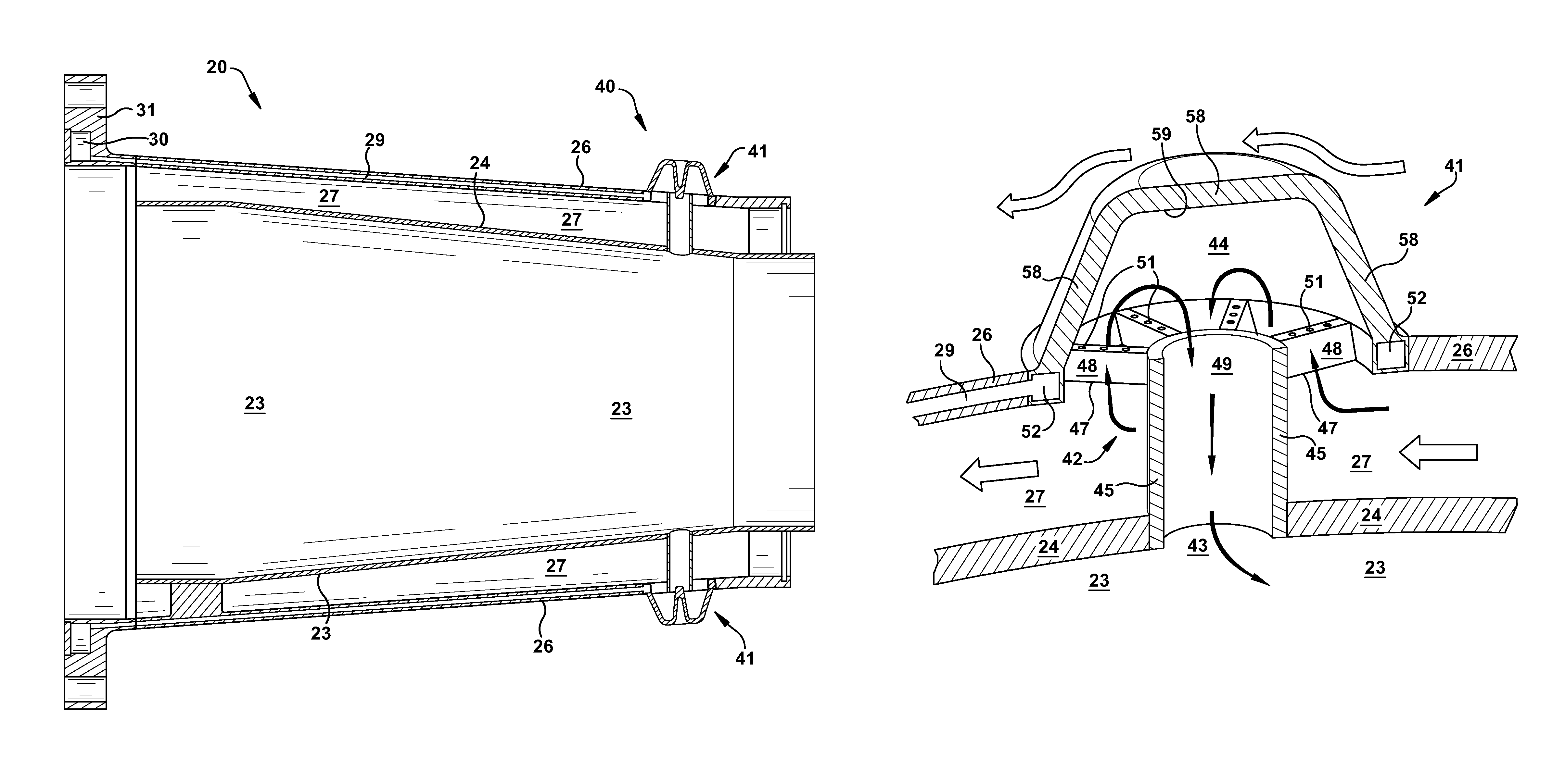
[0015]As an initial matter, in order to clearly delineate the invention of the current application, it may be necessary to select terminology that refers to and describes certain parts or machine components within a combustion turbine engine. Whenever possible, common industry terminology will be used and employed in a manner consistent with its accepted meaning. However, it is meant that any such terminology be given a broad meaning and not narrowly construed such that the meaning intended herein and the scope of the appended claims is unreasonably restricted. Those of ordinary skill in the art will appreciate that often a particular component may be referred to using several different terms. In addition, what may be described herein as being single part may include and be referenced in another context as consisting of multiple components, or, what may be described herein as including multiple components may be referred to elsewhere as a single part. As such, in understanding the s...


PUM


Abstract

An assembly for use in a fuel injection system within a combustor of a combustion turbine engine is described. The assembly may include: a first port formed through an outer radial wall of the combustor and a second port formed through an inner radial wall. A plenum may be formed about the first port. A tube may be formed that has a first end positioned within the first port and a second end positioned within the second port. At the first end, the tube may be sized smaller than the first port such that two passages are defined therethrough: a first passage defined about an exterior of the tube; and a second passage defined through an interior of the tube.

Description

BACKGROUND OF THE INVENTION[0001]The present invention relates to combustion turbine engines, and more particularly, to fuel injectors disposed downstream of primary fuel nozzles in the combustion systems.[0002]Multiple designs exist for staged combustion in combustion turbine engines, but most are complicated assemblies consisting of a plurality of tubing and interfaces. One kind of staged combustion used in combustion turbine engines is often referred to as “late lean injection.” In this type of staged combustion, late lean fuel injectors are located downstream of the primary fuel nozzle. As one of ordinary skill in the art will appreciate, combusting a fuel / air mixture at this downstream location may be used to improve NOx performance. NOx, or oxides of nitrogen, is one of the primary undesirable air polluting emissions produced by combustion turbine engines that burn conventional hydrocarbon fuels. The late lean injection may also function as an air bypass, which may be used to ...

Claims


Application Information

Patent Timeline
Patent Type & Authority Patents(United States)
IPC IPC(8): F02C1/00F23R3/28F23R3/04F23R3/34
CPCF23R3/045F23R3/286F23R3/346
Inventor CHEN, WEISTOIA, LUCAS JOHNDICINTIO, RICHARD MARTIN
Owner GE INFRASTRUCTURE TECH INT LLC
Why Eureka
Try Eureka