Flexible display device with stoppable hinge

a display device and hinge technology, applied in the field of display devices, can solve the problems of deterioration of design properties of display devices and damage to flexible display panels

Active Publication Date: 2018-03-06
SHARP KK
View PDF35 Cites 28 Cited by
  • Summary
  • Abstract
  • Description
  • Claims
  • Application Information

AI Technical Summary

Benefits of technology

[0021]According to the technology disclosed in this specification, a flexible display panel is less likely to be damaged without deteriorating visibility and design properties.

Problems solved by technology

During the rotation, if the angle formed by the two adjacent display support portions is greater than a predetermined value, the flexible display panel may be damaged.
Therefore, the projection shaft may obstruct a user's view when the user sees an image on the display surface of the flexible display panel and the design properties of the display device may be deteriorated.

Method used


Image

  • Flexible display device with stoppable hinge
  • Flexible display device with stoppable hinge
  • Flexible display device with stoppable hinge

Examples


first embodiment

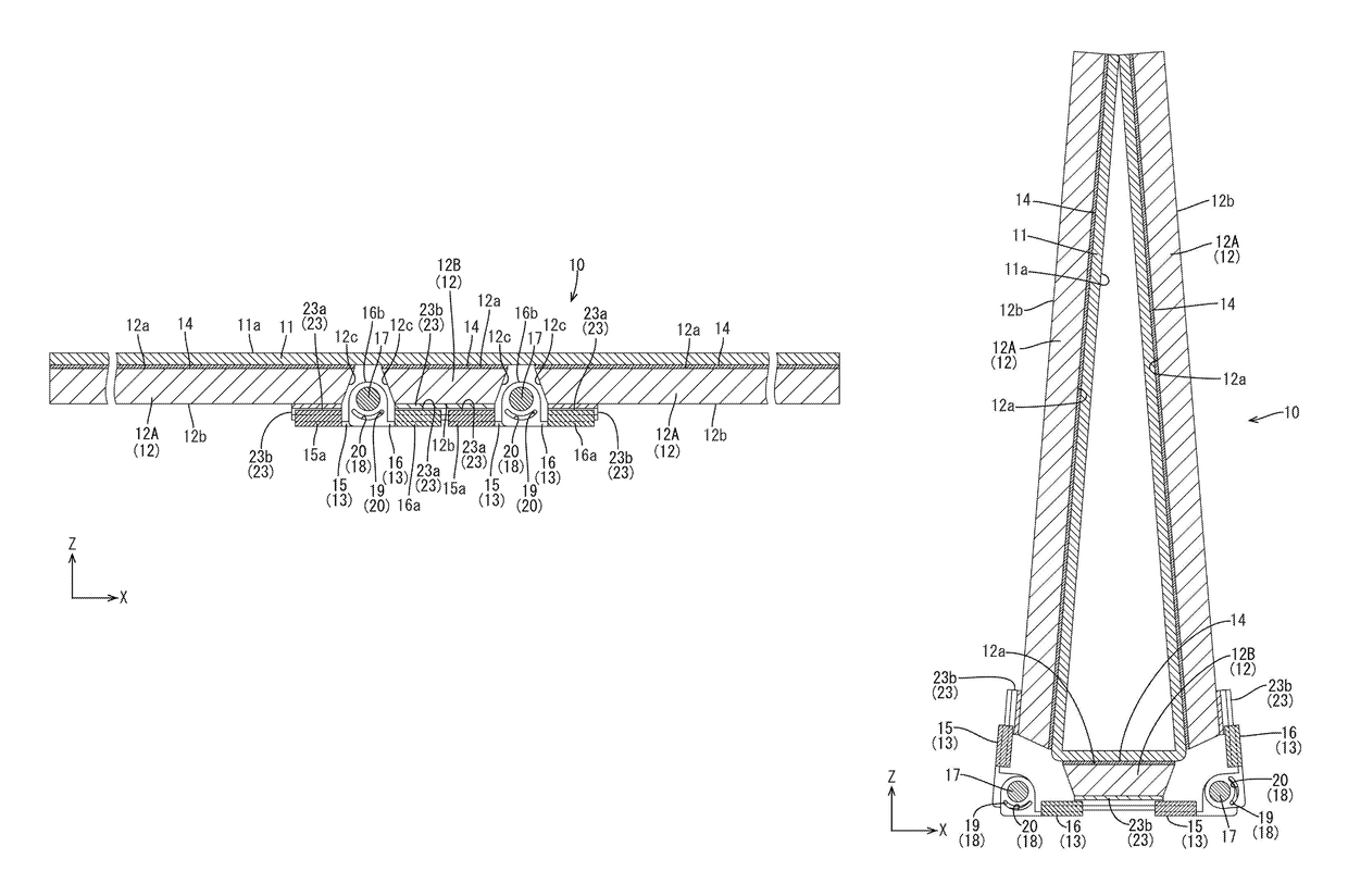
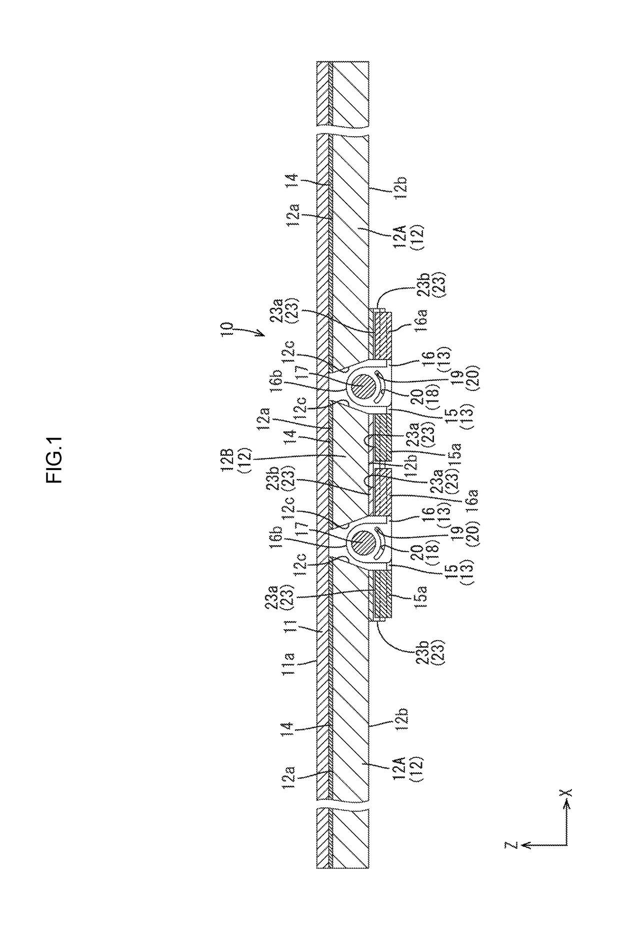
[0047]A first embodiment of the present technology will be described with reference to FIGS. 1 to 7. A display device 10 including a flexible display panel 11 will be described in the present embodiment. X-axis, Y-axis and Z-axis may be indicated in some of the drawings. The axes in each drawing correspond to the respective axes in other drawings. An up-down direction is referred with reference to FIGS. 1 and 3 and an upper side is a front-surface side and a lower side is a rear-surface side in FIGS. 1 and 3.

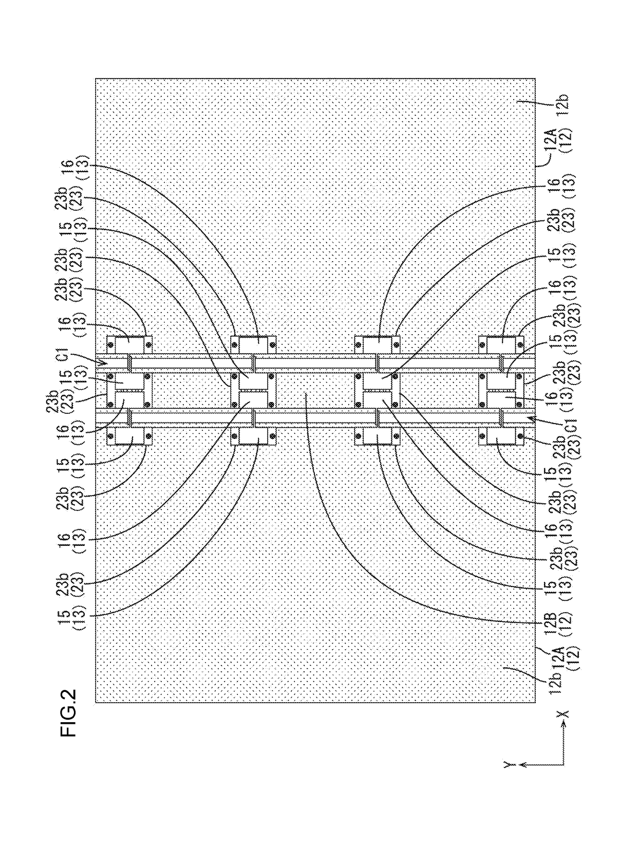
[0048]As illustrated in FIGS. 1 and 2, the display device 10 includes a flexible display panel 11, display support portions 12, and hinge portions 13. The flexible display panel 11 has flexibility and includes a display surface 11a where images appear. The display support portions 12 support the flexible display panel 11 from a side opposite to the display surface 11a side. The hinge portions 13 rotatably support the display support portions 12 that are adjacent to each other wh...

second embodiment

[0068]A second embodiment will be described with reference to FIG. 8. The second embodiment includes a fixing layer 114 having a different forming area. Similar configurations, operations, and effects to the first embodiment will not be described.

[0069]As illustrated in FIG. 8, the fixing layer 114 is applied on a most part of a support surface 112a of each display support portion 112 and is not applied on a part of the support surface 112a. Specifically, each of the display support portions 112 has no fixing layer 114 on an end portion thereof near the bending portion of a folded flexible display panel 111. The end portion of the support surface 112a near the bending portion is a fixing layer 114 non-forming area and a most part of the support surface 112a except for the end portion near the bending portion is a fixing layer 114 forming area. Specifically, the fixing layer 114 non-forming area in each main display support portion 112A is an area of 5 mm from the edge thereof near t...

third embodiment

[0071]A third embodiment of the present technology will be described with reference to FIGS. 9 to 11. In the third embodiment, the number of display support portions 212 is altered from that in the first embodiment. Similar configurations, operations, and effects to the first embodiment will not be described.

[0072]As illustrated in FIGS. 9 and 10, a display device 210 of the present embodiment includes four display support portions 212 that are arranged in a row when a flexible display panel 211 is in a flat state. The flexible display panel 211 that is supported by the four display support portions 212 is bent at borders of the display support portions 212. In the present embodiment, the flexible display panel 211 has three bending portions (see FIG. 11). The four display support portions 212 include two main display support portions 212A and two sub-display support portions 212B, and the two sub-display support portions 212B are arranged between the two main display support portio...


PUM

PropertyMeasurementUnit
sizeaaaaaaaaaa
sizeaaaaaaaaaa
thicknessaaaaaaaaaa

Abstract

A display device 10 includes a flexible display panel having a display surface 11a and flexibility, display support portions 12 supporting the flexible display panel from a side opposite to the display surface 11a side, a hinge portion 13 supporting the two adjacent display support portions 12 to be rotatable, and an angle restricting portion 18 mounted on each of hinge parts 15, 16 and including at least a stopper projection 19 and a stopper hole 20 that are stopped by each other when an angle formed by the two adjacent display supporting portions 12 reaches a predetermined value, the two adjacent display supporting portions 12 being rotated according to bending of the flexible display panel 11 from the flat state and the angle being formed by the two adjacent display supporting portions 12 that are rotated, and the angle restricting portion 18 restricting the angle.

Description

TECHNICAL FIELD[0001]The present invention relates to a display device.BACKGROUND ART[0002]Display devices using flexible and foldable display panels have been developed and one disclosed in Patent Document 1 has been known. The display device described in Patent Document 1 includes a pair of cases where a flexible display panel is mounted, and a hinge portion that connects the cases so as to be rotatable. The hinge portion includes a projected shaft portion. The projected shaft portion projects to an inner side of the display device where the flexible display panel is mounted. When the flexible display panel is folded, the side edge portion of the flexible display panel is wound around the outer peripheral surface of the projected shaft portion and the bending portion of the flexible portion has a diameter so that the display circuit is not damaged.RELATED ART DOCUMENTPatent Document[0003]Patent Document 1: Japanese Unexamined Patent Application Publication No. 2013-50547Problem to...

Claims


Application Information

Patent Timeline
Patent Type & Authority Patents(United States)
IPC IPC(8): G06F1/16G02F1/1333E05D3/00H04M1/02
CPCG06F1/1652E05D3/00H04M1/0268G06F1/16G02F1/133305G09F9/00G09F9/30G06F1/1601G06F1/1616G06F1/1681G09F9/301H04M1/022H10K77/111H10K2102/311
Inventor WATANABE, NORIKOITOH, AKIKO
Owner SHARP KK
Why Eureka
Try Eureka