Transfer path altering device

a technology of changing device and transfer path, which is applied in the direction of thin material processing, domestic applications, other domestic articles, etc., can solve the problems of deteriorating processing efficiency and product manufacturing efficiency, increasing the frequency of failure and necessary maintenance work, and increasing the frequency of failure and maintenance work. , to achieve the effect of reducing transportation speed

Active Publication Date: 2018-04-03
KAO CORP
View PDF18 Cites 0 Cited by
  • Summary
  • Abstract
  • Description
  • Claims
  • Application Information

AI Technical Summary

Benefits of technology

[0008]The present invention also provides a processing method for performing a predetermined processing to an object that is being transported, the transported object processing method involving: temporarily reducing the transportation speed of the transported object or temporarily stopping the transported object by the aforementioned transportation path changing device; and in this state, performing processing to the transported object.

Problems solved by technology

Unfortunately, in the processing device of Patent Literature 1, in order to achieve the temporarily-halted state while keeping the work transportation speed high, a large load has to be applied to e.g. the servomotor that drives the pass-line rollers etc. for driving the first and second moving elements.
This results in an increase in the frequency of failure and necessary maintenance work.
On the other hand, in order to prevent large loads from being applied to e.g. the servomotor that drives the first and second moving elements, the work transportation speed needs to be reduced, which will deteriorate processing efficiency and product manufacturing efficiency.

Method used


Image

  • Transfer path altering device
  • Transfer path altering device
  • Transfer path altering device

Examples


first embodiment

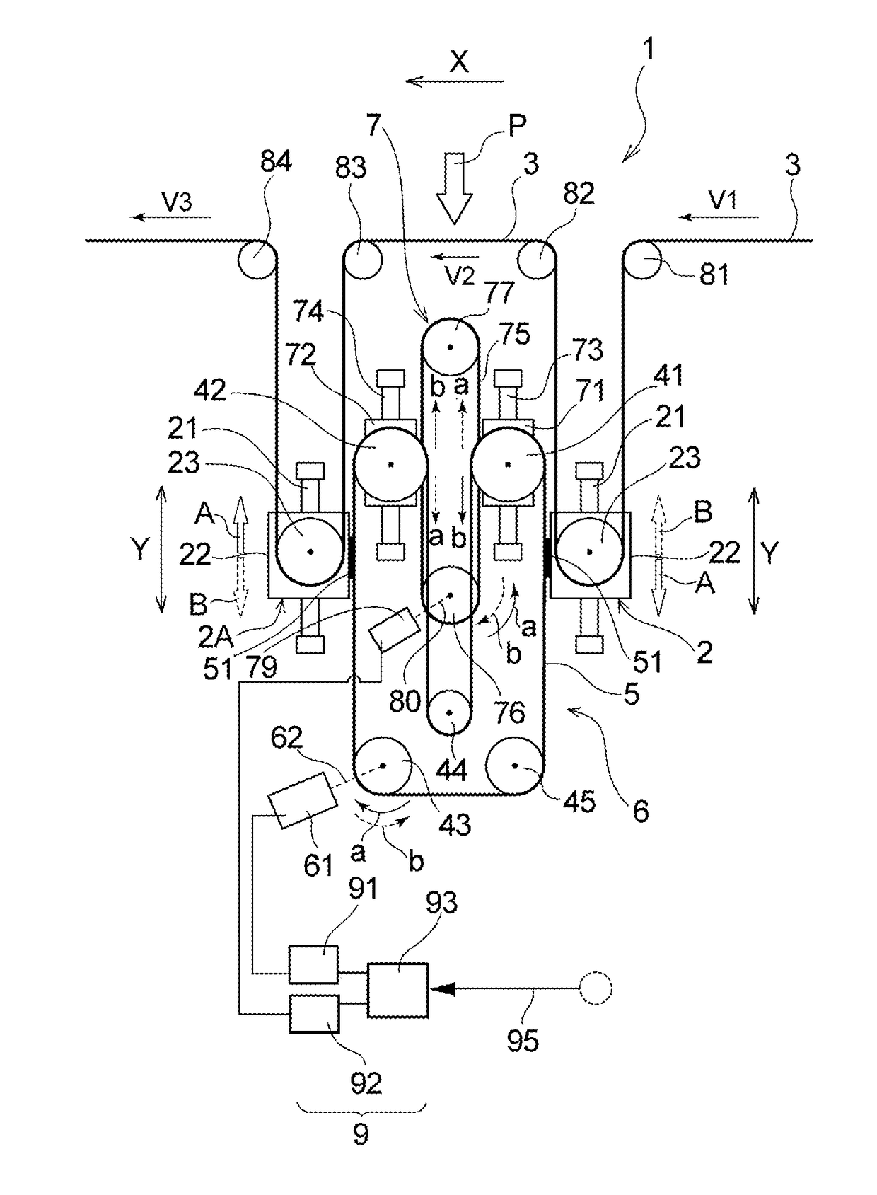
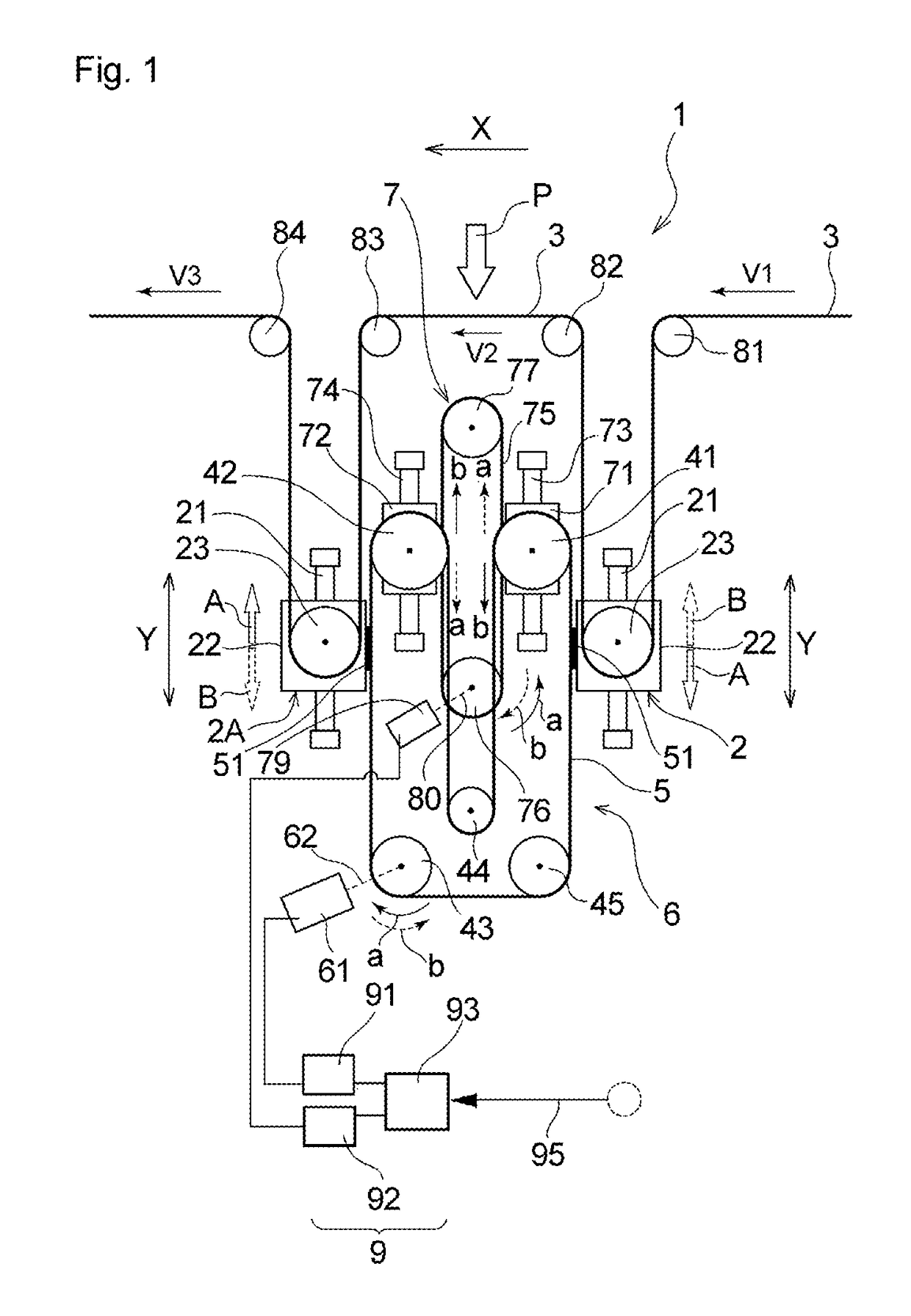
[0018]As illustrated in FIG. 1, a transportation path changing device 1 according to the present invention is a transportation path changing device that temporarily changes the transportation path of a continuous sheet-like object 3 that is being transported, and includes: an oscillating section 2 that oscillates in an intersecting direction Y intersecting with a flow direction X of the transported object 3, and that increases / decreases the length of the transportation path of the transported object; a belt rotating means 6 (first moving means) that is connected to the oscillating section 2, and that moves the oscillating section 2 in the intersecting direction Y; a belt moving means 7 (second moving means) that moves a portion or the entirety of the belt rotating means 6 (first moving means) in the intersecting direction Y; and a control section 9 that controls the belt rotating means 6 (first moving means) and the belt moving means 7 (second moving means).

[0019]As illustrated in F...

second embodiment

[0054]It should be noted that, as regards the drive source (servomotor 79 etc.) for moving the sliders 71, 72, a single drive source (servomotor etc.) may be provided for a plurality of sliders as in the present embodiment, or a drive source may be provided for each slider 71, 72 as in the second embodiment illustrated in FIG. 6.

[0055]Further, the device 1 of the present embodiment is configured such that the second belt 75 connected to the plurality of sliders 71, 72 is driven by the servomotor 79, and thereby both the sliders 71, 72 move in cooperation. By moving the sliders 71, 72 in cooperation, the oscillation of the oscillating sections 2, 2A can be controlled with high accuracy.

[0056]Next, other embodiments of the present invention will be described. As for the other embodiments, only features that are different from those of the first embodiment are described, and features that are the same are accompanied by the same reference signs and explanation thereof is omitted. The e...

third embodiment

[0059]In the transportation path changing device of the third embodiment, the reciprocating motion (oscillation) of the oscillating sections 2, 2A is achieved by the cooperation of the first and second linear motors. Thus, the motion speed and acceleration of each motor can be reduced, and the speed can be further increased compared to cases where each oscillating section 2, 2A is moved by a single linear motor. Further, by using a linear motor, the structure of the mechanism can be simplified and the number of components can be reduced, and thus, maintenance work can be reduced.

[0060]In a transportation path changing device according to a fourth embodiment, as illustrated in FIG. 8, the oscillating section 2 on the upstream side of the processing section P and the oscillating section 2A on the downstream side of the processing section P are each made to oscillate by the cooperation of a belt rotating means 6 (first moving means) and a linear motor 85 (second moving means). More spe...


PUM

PropertyMeasurementUnit
lengthaaaaaaaaaa
distanceaaaaaaaaaa
speedaaaaaaaaaa

Abstract

A transportation path changing device (1) of the invention is a transportation path changing device that changes a transportation path of a continuous sheet-like object (3) that is being transported. The device includes: an oscillating section (2) that oscillates in an intersecting direction Y intersecting with a flow direction X of the transported object, and that increases / decreases the length of the transportation path of the transported object (3); a first moving means (6) that is connected to the oscillating section (2), and that moves the oscillating section (2) in the intersecting direction Y; a second moving means (7) that moves a portion or the entirety of the first moving means (6) in the intersecting direction Y; and a control section (9) that controls the first moving means (6) and the second moving means (7).

Description

TECHNICAL FIELD[0001]The present invention relates to a transportation path changing device.BACKGROUND ART[0002]In a conventional technique for manufacturing various products such as disposable diapers, a reduced-speed region where the transportation speed for transporting a transported object—such as a constituent member of the product or an intermediate that is in the course of being manufactured—is partially reduced, or dropped to zero, is provided in midstream of a transportation path for transporting the transported object, and various types of processing are performed to the transported object in the reduced-speed region.[0003]For example, Patent Literature 1 discloses a processing device wherein first and second moving elements that move back and forth while guiding a work are provided on each of the upstream side and the downstream side of a processing section, and the first and second moving elements are interlocked by an interlocking section that seesaws back and forth, an...

Claims


Application Information

Patent Timeline
Patent Type & Authority Patents(United States)
IPC IPC(8): B65H20/24B65H23/18B65H20/30
CPCB65H20/24B65H20/30B65H23/18B65H2801/57B65H2301/4491B29L2031/4878B29C66/1122B29C66/83411B29C66/83511B29C66/431B29C66/232B29C65/18B29C65/087
Inventor OKU, SHOGOKOKUBO, MAKOTO
Owner KAO CORP
Why Eureka
Try Eureka