Post-processing device and image forming system

a technology of post-processing device and image forming system, which is applied in the direction of electrographic process, grain treatment, instruments, etc., can solve the problems of degrading product quality and affecting the shape of paper pieces after being sli

Active Publication Date: 2015-09-24
KONICA MINOLTA INC
View PDF7 Cites 5 Cited by
  • Summary
  • Abstract
  • Description
  • Claims
  • Application Information

AI Technical Summary

Benefits of technology

[0009]To achieve at least one of the abovementioned objects, a post-processing device of the present invention has a sheet transporting section that transports one or more sheets, a cutting section that cuts the sheet along a transporting direction of the sheet being transported at the sheet transporting section, and a paper piece transporting section that transports a paper piece cut at the cutting section, and a transporting speed of the paper piece transporting section is set lower than a transporting speed of the sheet transporting section.

Problems solved by technology

However, if the stiffness of the cut sheet is low or if a slit width is small, the shape of the paper piece after being slit is not maintained, which makes the paper piece after being slit proceed in a direction away from the sheet being transported.
Therefore, a problem arises that action of pulling the paper piece from the cut face occurs, which causes scuffing on the cut face and degrades product quality.

Method used


Image

  • Post-processing device and image forming system
  • Post-processing device and image forming system
  • Post-processing device and image forming system

Examples


Embodiment Construction

[0039]Next, embodiments of the present invention will be described based on the accompanying drawings.

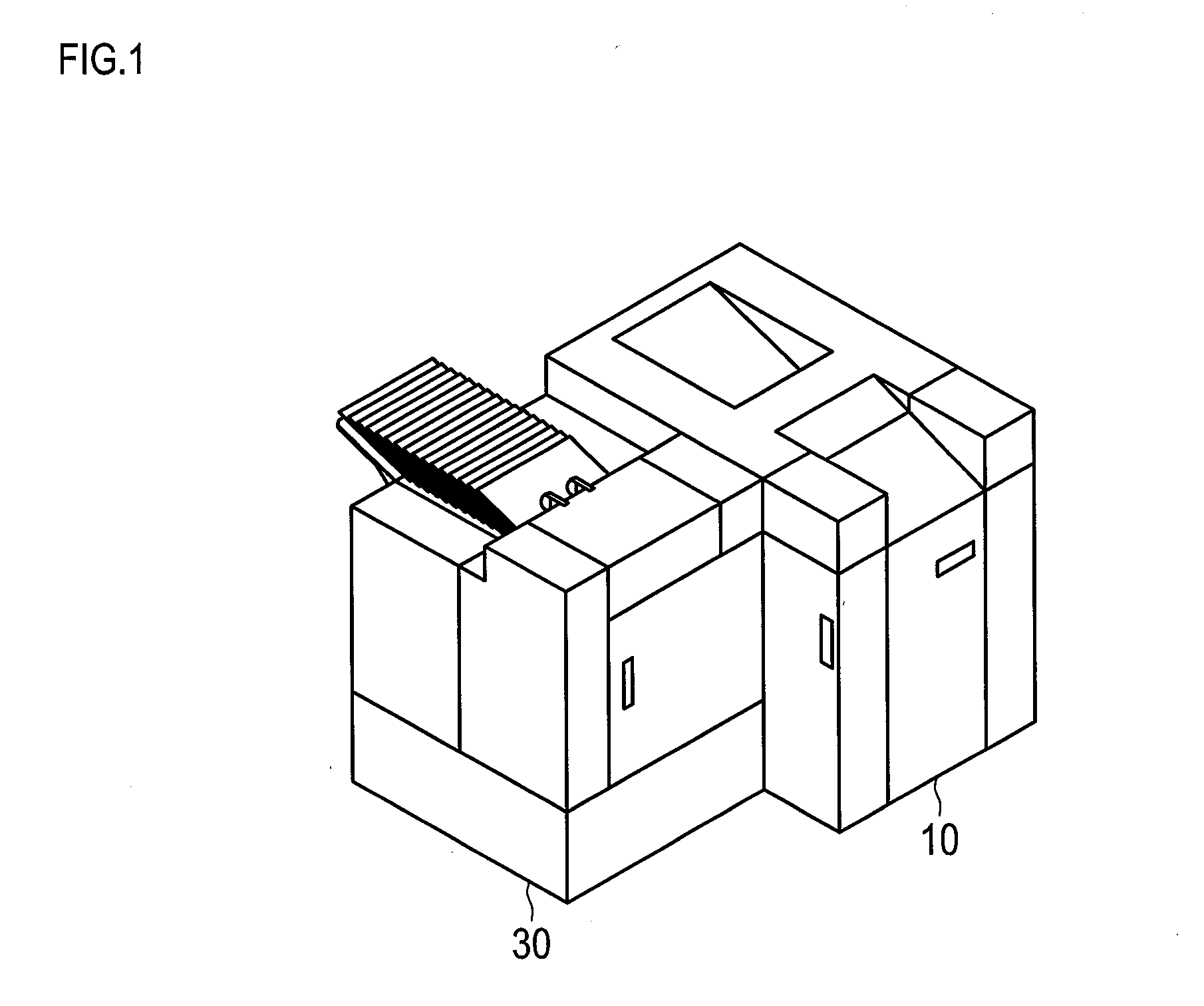
[0040]An image forming system 1 including an image forming device 10 and a post-processing device 30 will be described below.

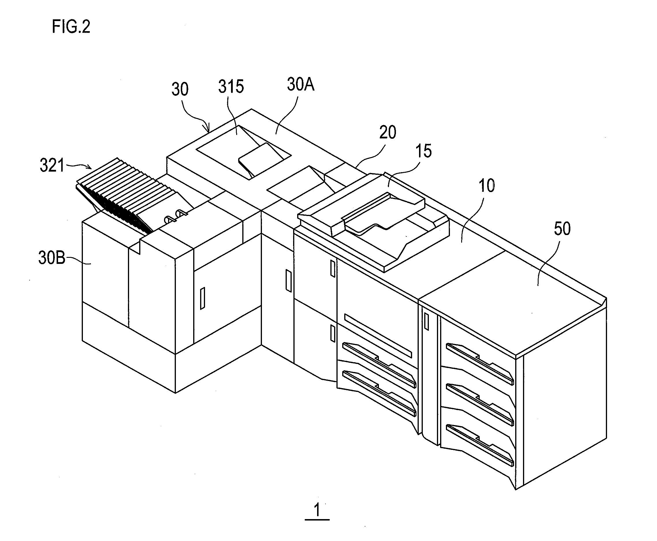
[0041]In the image forming system illustrated in FIG. 1, the image forming device 10 that forms images and the post-processing device 30 that performs booklet processing of performing saddle stitching bookbinding on sheets on which the images are formed at the image forming device are mechanically and electrically connected. Further, FIG. 2 illustrates a modified example of the image forming system 1 in which a reverse transporting device 20 is disposed between the image forming device 10 and the post-processing device 30, and a large capacity paper feed tray 50 is disposed and connected at an upstream side of the image forming device 10. The post-processing device 30 has a front block 30A and a lateral block 30B.

[0042]An outline of a mechanical configuration ...


PUM

PropertyMeasurementUnit
transporting speedaaaaaaaaaa
linear velocityaaaaaaaaaa

Abstract

A post-processing device includes a sheet transporting section that transports one or more sheets, a cutting section that cuts the sheet along a transporting direction of the sheet being transported by the sheet transporting section and a paper piece transporting section that transports a paper piece cut by the cutting section, and a transporting speed of the paper piece transporting section is set lower than a transporting speed of the sheet transporting section.

Description

CROSS-REFERENCE TO RELATED APPLICATIONS[0001]The present application claims priority under 35 U.S.C. §119 to Japanese Patent Application No. 2014-055164, filed Mar. 18, 2014. The contents of this application are incorporated herein by reference in their entirety.BACKGROUND OF THE INVENTION[0002]1. Field of the Invention[0003]The present invention relates to a post-processing device including a cutting section that cuts part of a sheet and an image forming system including the post-processing device.[0004]2. Description of the Related Art[0005]When a post-processing device performs post-processing on a sheet on which an image has been formed in an image forming device, there is a case where part of the sheet is cut at a top and a bottom of the sheet so that the size of the sheet is adjusted. In a field of shredders for cutting sheets, by rotating a cutting mechanism other than transportation at a higher speed, it is possible to realize more reliable cutting (see, for example, Interna...

Claims


Application Information

Patent Timeline
Patent Type & Authority Applications(United States)
IPC IPC(8): B65H35/02B26D7/18
CPCB26D7/18B65H35/02B26D1/245B26D7/2635B41J11/70B26D2007/005B65H2301/515323B65H2301/5155B65H2701/1315Y10T83/2087B65H2513/20B65H2220/02B41F13/58B65H2801/27G03G2215/00814B02C18/22B02C18/18B02C18/06
Inventor KIRIYAMA, TOMOHIROTOYOIZUMI, TERUHIKOOTSU, SHOHEI
Owner KONICA MINOLTA INC
Why Eureka
Try Eureka