Supercharge Your Innovation With Domain-Expert AI Agents!

Apparatus for manufacturing fluorescent layers

a technology of fluorescent film and adhesive, which is applied in the direction of electric lighting source, electric light source, semiconductor device, etc., can solve the problems of difficult to reduce the color deviation of white light, fluorescent film is not effectively attached to the desired position, and the artificial light source cannot be sold, etc., and achieves excellent adhesive force

Active Publication Date: 2018-04-10
LIGHTIZER KOREA
View PDF14 Cites 0 Cited by
  • Summary
  • Abstract
  • Description
  • Claims
  • Application Information

AI Technical Summary

Benefits of technology

The solution effectively reduces color deviation and improves adhesive reliability, increasing yield by allowing direct attachment and testing of fluorescent layers on light-emitting diodes without additional processing steps, ensuring compliance with MacAdam's Ellipse Rule criteria.

Problems solved by technology

Currently, in the United States, an artificial light source is not allowed to be sold if the artificial light source does not comply with three steps of the MacAdam Ellipse Rule.
If the fluorescent film is attached to a light-emitting diode, the fluorescent film is not effectively attached to a desired position of the light-emitting diode due to electrostatic force or adhesive force occurring between the fluorescent materials and the film made of resin.
Accordingly, it is difficult to reduce a color deviation in white light, and a reliability problem is generated due to poor adhesive force between the light-emitting diode and the fluorescent film.
As a result, there is a problem in that an additional process is added.

Method used


Image

  • Apparatus for manufacturing fluorescent layers
  • Apparatus for manufacturing fluorescent layers
  • Apparatus for manufacturing fluorescent layers

Examples


Embodiment Construction

[0022]Exemplary embodiments of the present invention are described in detail with reference to the accompanying drawings.

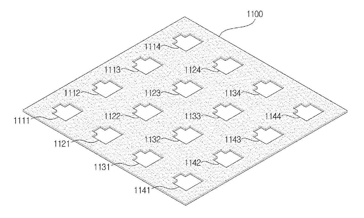
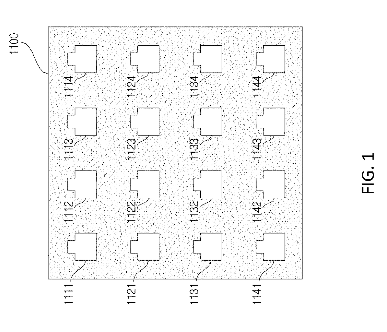
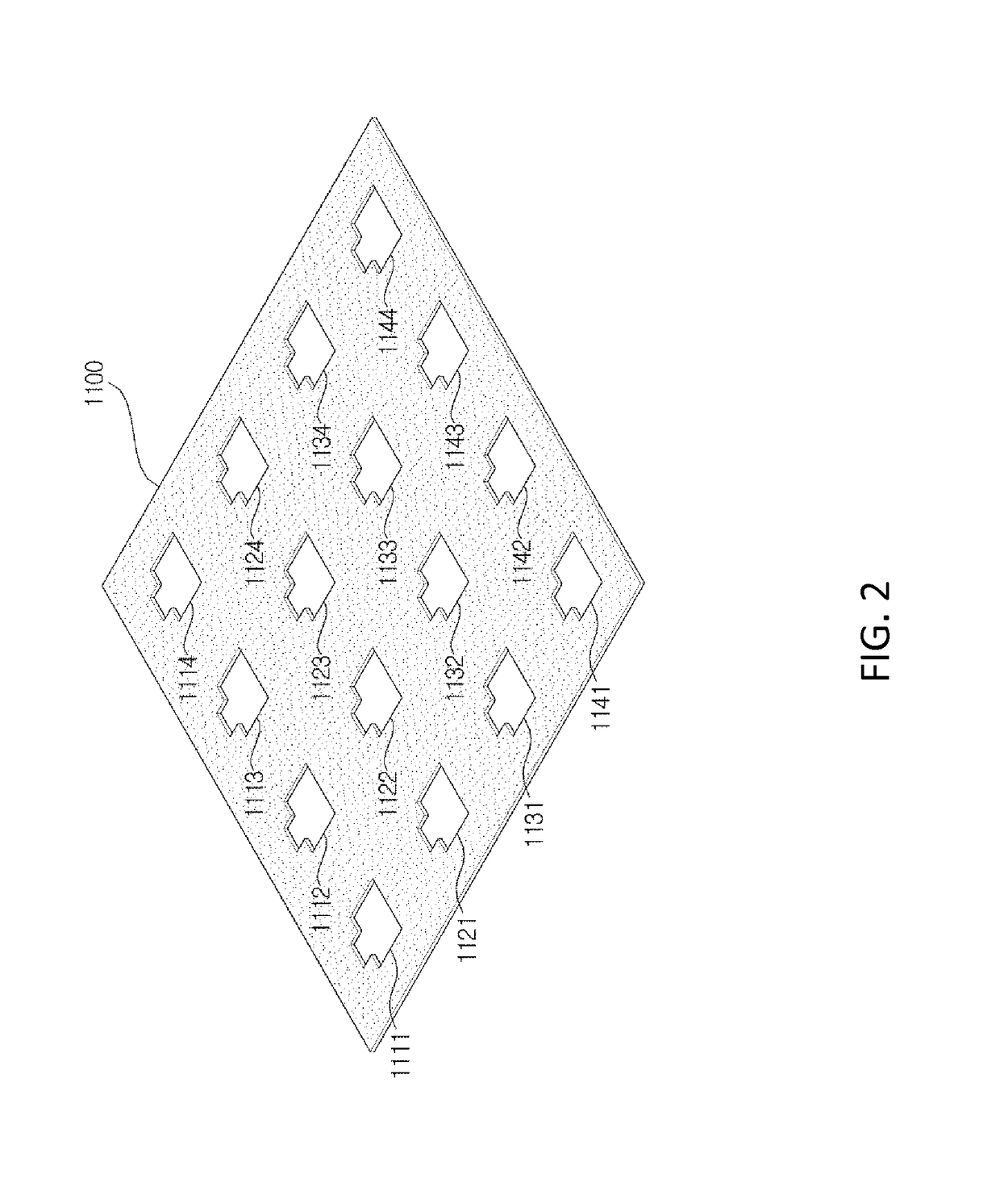
[0023]An apparatus for manufacturing fluorescent layers in accordance with an embodiment of the present invention, as shown in FIG. 1 or 2, may include a vertical frame 1100 and a plurality of fluorescent layer pattern holes 1111 to 1114, 1121 to 1124, 1131 to 1134, and 1141 to 1144, each formed in the form of a fluorescent layer pattern in a direction vertical to the vertical frame 1100, within a specific region of the vertical frame 1100.

[0024]Each of the plurality of fluorescent layer pattern holes 1111 to 1114, 1121 to 1124, 1131 to 1134, and 1141 to 1144 can have a shape of pad electrodes. In particular, as shown in FIG. 1 or 2, rectangular forms are included on the upper left and upper right sides of each of the plurality of fluorescent layer pattern holes 1111 to 1114, 1121 to 1124, 1131 to 1134, and 1141 to 1144. When fluorescent layers are manufactured by...


PUM


Abstract

The present invention relates to an apparatus for manufacturing fluorescent layers and, more particularly, to an apparatus for manufacturing fluorescent layers, which converts light from a light-emitting diode into white light by varying a wavelength of the light emitted from the light-emitting diode. The present invention provides the apparatus for manufacturing fluorescent layers includes a vertical frame and a fluorescent layer pattern hole formed in a direction vertical to the vertical frame in a fluorescent layer pattern form within the vertical frame.

Description

CROSS REFERENCE TO RELATED APPLICATION[0001]The present application claims the benefit of Korean Patent Application No. 10-2013-0068152 filed in the Korean Intellectual Property Office on Jun. 14, 2013, the entire contents of which are incorporated herein by reference.BACKGROUND OF THE INVENTION[0002]1. Technical Field[0003]The present invention relates to an apparatus for manufacturing fluorescent layers and, more particularly, to an apparatus for manufacturing fluorescent layers, which converts light from a light-emitting diode into white light by varying a wavelength of the light emitted from the light-emitting diode.[0004]2. Description of the Related Art[0005]Recently, a light-emitting diode in which Al or In has been added to GaN has been in the spotlight owning to longer lifespan, low power consumption, excellent brightness, and eco-friendly factors not harmful to the human being, as compared with a conventional incandescent electric lamp. In particular, a light-emitting diod...

Claims


Application Information

Patent Timeline
Patent Type & Authority Patents(United States)
IPC IPC(8): H05B33/10
CPCH05B33/10H01L2933/0041H01L21/48H01L21/50H01L33/50
Inventor MIN, JAE SIKJANG, JAE YOUNGLEE, JAE YEOPCHO, BYOUNG GU
Owner LIGHTIZER KOREA
Features
  • R&D
  • Intellectual Property
  • Life Sciences
  • Materials
  • Tech Scout
  • Unparalleled Data Quality
  • Higher Quality Content
  • 60% Fewer Hallucinations
Learn More