Mechanical seal

a mechanical seal and sealing face technology, applied in the direction of engine seals, mechanical apparatus, engine components, etc., can solve the problems of inability to catch the sealed fluid, leakage of outward flow of fluid, and insufficient lubrication of sealing faces during start-up and after start-up

Active Publication Date: 2018-05-29
EAGLE INDS
View PDF22 Cites 6 Cited by
  • Summary
  • Abstract
  • Description
  • Claims
  • Application Information

AI Technical Summary

Benefits of technology

[0051](1) According to the first through fifth aspects, when stationary, there will be a solid contact state between the sealing faces of the fixed ring and the rotating ring, and therefore leakage is prevented by the sealing faces, which are continuous in the circumferential direction, and sealing performance is thereby maintained. Also, during start-up, the catching of the sealed fluid in the spaces within the sealed-fluid-accommodating blocks makes it possible to quickly form a lubrication fluid film, and lower the sliding torque of the sealing faces and to reduce friction. During operation, the sealed fluid will be caught in the sealed-fluid-accommodating blocks provided with the intake pumping parts, the sealed fluid will be sent in through the sealing faces to the discharge pumping parts located at positions separated apart by the sealing faces, and the sealed fluid will be returned to the sealed fluid side, making it possible to ensure lubrication performance of the sealing faces and possible to prevent leakage and maintain sealing performance.
[0052](2) According to the sixth through ninth aspects, the periodic structure of linear irregularities of the pumping parts can be easily and accurately provided.
[0053](3) According to the tenth aspect, the effect of (1) above can be optimized.
[0054](4) According to the eleventh through thirteenth aspects, it is even further possible in the intake pumping parts for the sealed fluid to be caught and sent to the discharge pumping parts, and even further possible in the discharge pumping parts for the sealed fluid sent therein to be returned to the sealed fluid side, and thus sealing performance and lubrication performance can be even further enhanced.
[0055](5) According to the fourteenth aspect, because the pumping capacity of the intake pumping parts and the pumping capacity of the discharge pumping parts can be set to be equal or the pumping capacity of either one can be set to be greater, the intake or discharge pumping capacity can be freely set in accordance with the mode of use of the mechanical seal.
[0056]Also, according to the fifteenth through seventeenth aspects, because the discharge capacity of the discharge pumping parts can be set to be greater than the intake capacity of the intake pumping parts, the sealed fluid flowing in from the intake pumping parts and elsewhere is returned to the sealed fluid side from the discharge pumping parts and is prevented from leaking out to the atmosphere side.

Problems solved by technology

However, in such a case, positive pressure occurs between the sealing faces, and therefore the fluid flows out from the positive pressure portion to the outside of the sealing face.
This outward flow of fluid qualifies as leakage in cases of sealing.
Additionally, since the grating parts 73a, 73b are formed substantially flush with the sealing face 72, a problem emerges in that the grating parts 73a, 73b are unable to catch the sealed fluid, and in that the sealing faces cannot be adequately lubricated during start-up and after start-up.

Method used


Image

  • Mechanical seal
  • Mechanical seal
  • Mechanical seal

Examples


first embodiment

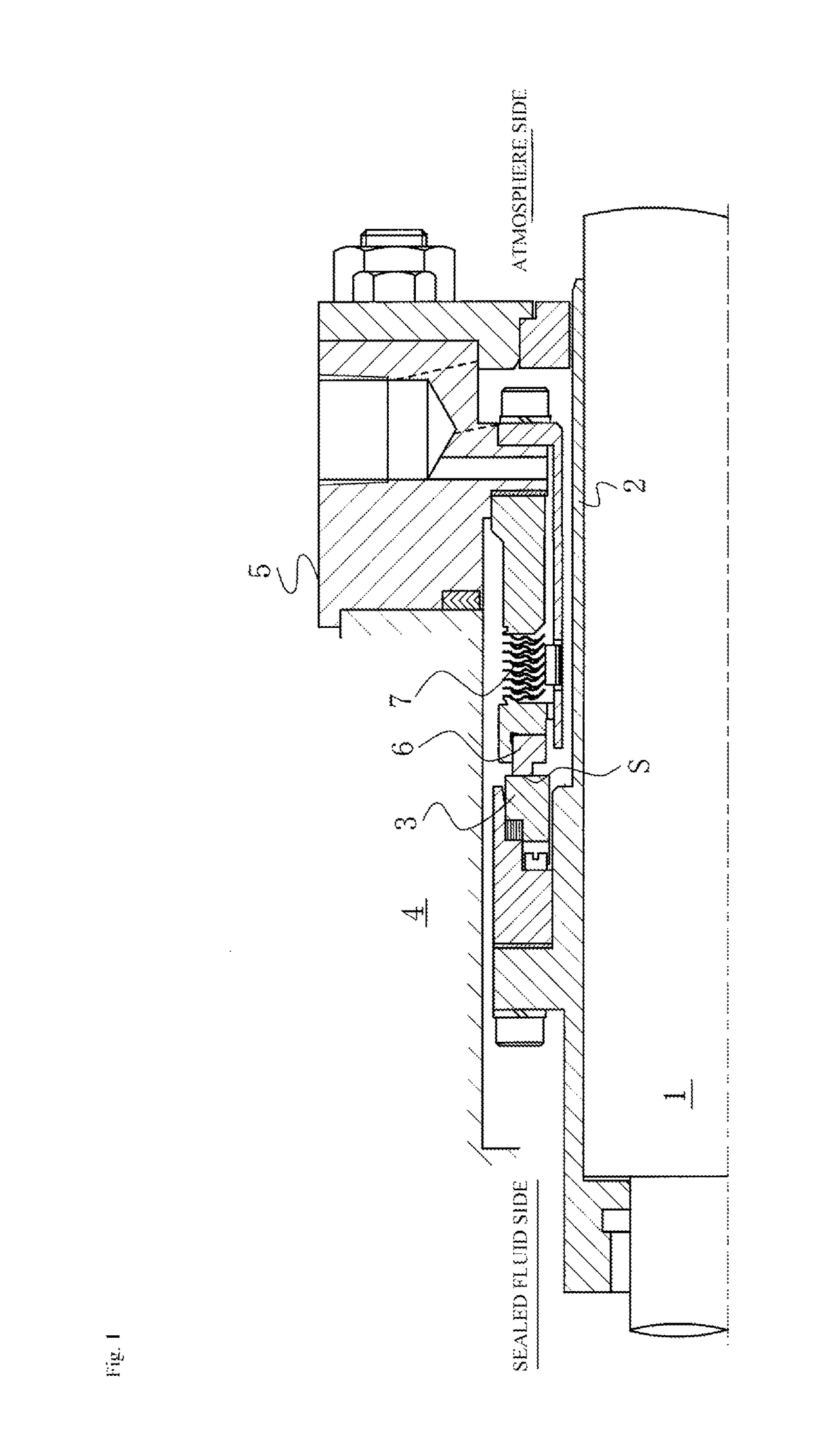
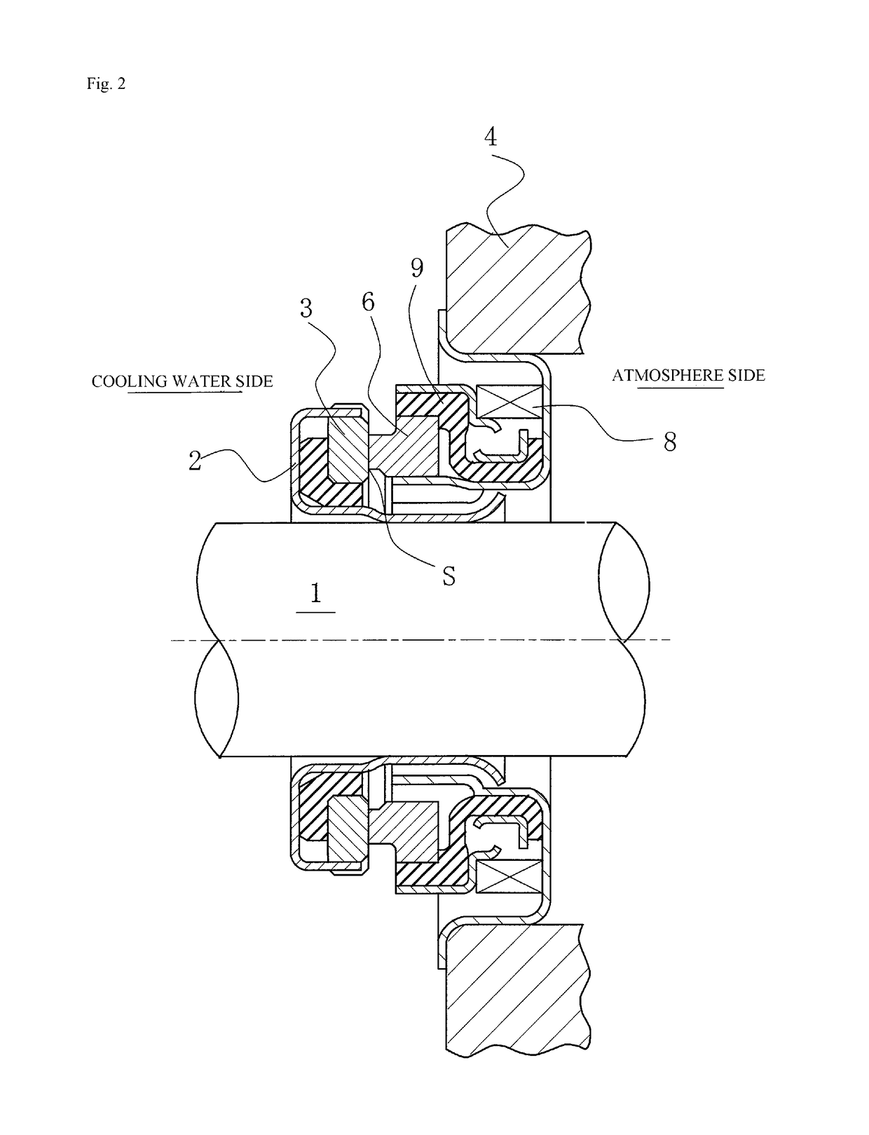
[0081]FIG. 3 is a plan view illustrating a mechanical seal as in a first embodiment of the present invention, as exemplified in FIGS. 1 and 2, wherein the first embodiment illustrates a case where sealed-fluid-accommodating blocks and pumping parts are formed on the sealing face S of the fixed ring 6, which, of the sealing faces of the fixed ring 6 and the rotating ring 3, has the lesser width in the radial direction.

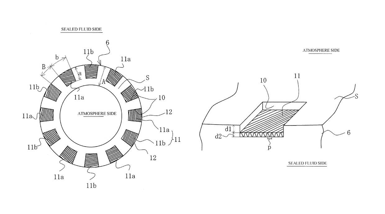
[0082]In FIG. 3, a plurality of sealed-fluid-accommodating blocks 10 separated in the circumferential direction are formed on the sealing face S of the fixed ring 6 so as to be a part of the sealing face S in the radial direction and to communicate directly to a sealed fluid accommodation space via an outer peripheral side 12.

[0083]In the case of an outside-type mechanical seal, in which the sealed fluid side exists on the inside of the rotating ring 3 and the fixed ring 6, the sealed-fluid-accommodating blocks 10 may also be formed so as to be a part of the sealing fac...

second embodiment

[0112]FIG. 6 is a cross-sectional view illustrating the sealed-fluid-accommodating blocks 10 and pumping parts 11 formed on the sealing face S of the fixed ring 6 of the mechanical seal as in the second embodiment of the present invention, as exemplified in FIGS. 1 and 2.

[0113]In the first embodiment, the pumping parts 11 were formed to be parallel to a plane orthogonal to the shaft in the circumferential direction and the radial direction; however, in FIG. 6, the intake pumping parts 11a formed on the bottom part of the sealed-fluid-accommodating blocks 10 are formed so that the linear irregularities thereof gradually become higher toward the direction R of rotation of the rotating ring 3, which is an opposing sliding member; the discharge pumping parts 11b are formed so that the linear irregularities thereof gradually become lower toward the direction R of rotation of the rotating ring 3, which is an opposing sliding member.

[0114]In this manner, in addition to the slope with respe...

third embodiment

[0118]FIG. 7 is a plan view illustrating a mechanical seal as in a third embodiment of the present invention, as exemplified in FIGS. 1 and 2, wherein this embodiment is a case where the sealed-fluid-accommodating blocks and pumping parts are formed on the sealing face of the rotating ring, which, of the sealing faces of the fixed ring and the rotating ring, has the greater width in the radial direction.

[0119]In FIG. 7, the plurality of sealed-fluid-accommodating blocks 10 separated in the circumferential direction are formed on the sealing face S of the rotating ring 3, which, of the sealing faces of the rotating ring 3 and the fixed ring 6, has the greater sealing face width in the radial direction. The plurality of sealed-fluid-accommodating blocks 10 are formed on a part of the sealing face S that does not include the radial outward and inward sides thereof, and are formed so that a part of the sealed fluid side of the sealed-fluid-accommodating blocks 10 is not covered by the o...


PUM


Abstract

A mechanical seal has a structure wherein a plurality of sealed-fluid-accommodating blocks separated in the circumferential direction are formed on either the sealing face of a fixed ring or the sealing face of a rotating ring so as to communicate with a sealed fluid accommodation space. Pumping parts for creating a pumping action due to the fixed ring and the rotating ring sliding while undergoing relative rotation are formed on a bottom part of the plurality of sealed-fluid-accommodating blocks. The pumping parts formed on the bottom parts of the plurality of sealed-fluid-accommodating blocks are provided with an intake pumping part which acts in a direction in which the sealed fluid is drawn in and a discharge pumping part which acts in a direction in which the sealed fluid is discharged.

Description

[0001]This application is the U.S. National Phase under 35 U.S.C. § 371 of International Application PCT / JP2012 / 069144, filed Jul. 27, 2012, which claims priority to Japanese Patent Application No. 2011-171414, filed Aug. 5, 2011. The International Application was published under PCT Article 21(2) in a language other than English.TECHNICAL FIELD[0002]The present invention relates to a mechanical seal used in automobiles, general industrial machinery, and other fields requiring seals; e.g., a mechanical seal used for sealing in a rotating shaft and housing for a water pump.BACKGROUND ART[0003]In order to maintain prolonged sealing performance in a mechanical seal, it is necessary to achieve the contradictory conditions of airtightness and lubricity. In recent years especially, there has been an even greater demand for lower friction in order to reduce mechanical loss while also preventing leakage of a sealed fluid, in part because of environmental measures. Friction can be reduced by...

Claims


Application Information

Patent Timeline
Patent Type & Authority Patents(United States)
IPC IPC(8): F16J15/34
CPCF16J15/3412F16J15/34
Inventor OSADA, HARUHIROINOUE, HIDEYUKIHOSOE, TAKESHIMORIMIYA, DAISUKETOKUNAGA, YUICHIRONEGISHI, YUTA
Owner EAGLE INDS
Why Eureka
Try Eureka