Mechanical seal
a mechanical seal and sealing face technology, applied in the direction of engine seals, mechanical apparatus, engine components, etc., can solve the problems of inability to catch the sealed fluid, leakage of outward flow of fluid, and inability to adequately lubricate the sealing face during start-up
- Summary
- Abstract
- Description
- Claims
- Application Information
AI Technical Summary
Benefits of technology
Problems solved by technology
Method used
Image
Examples
first embodiment
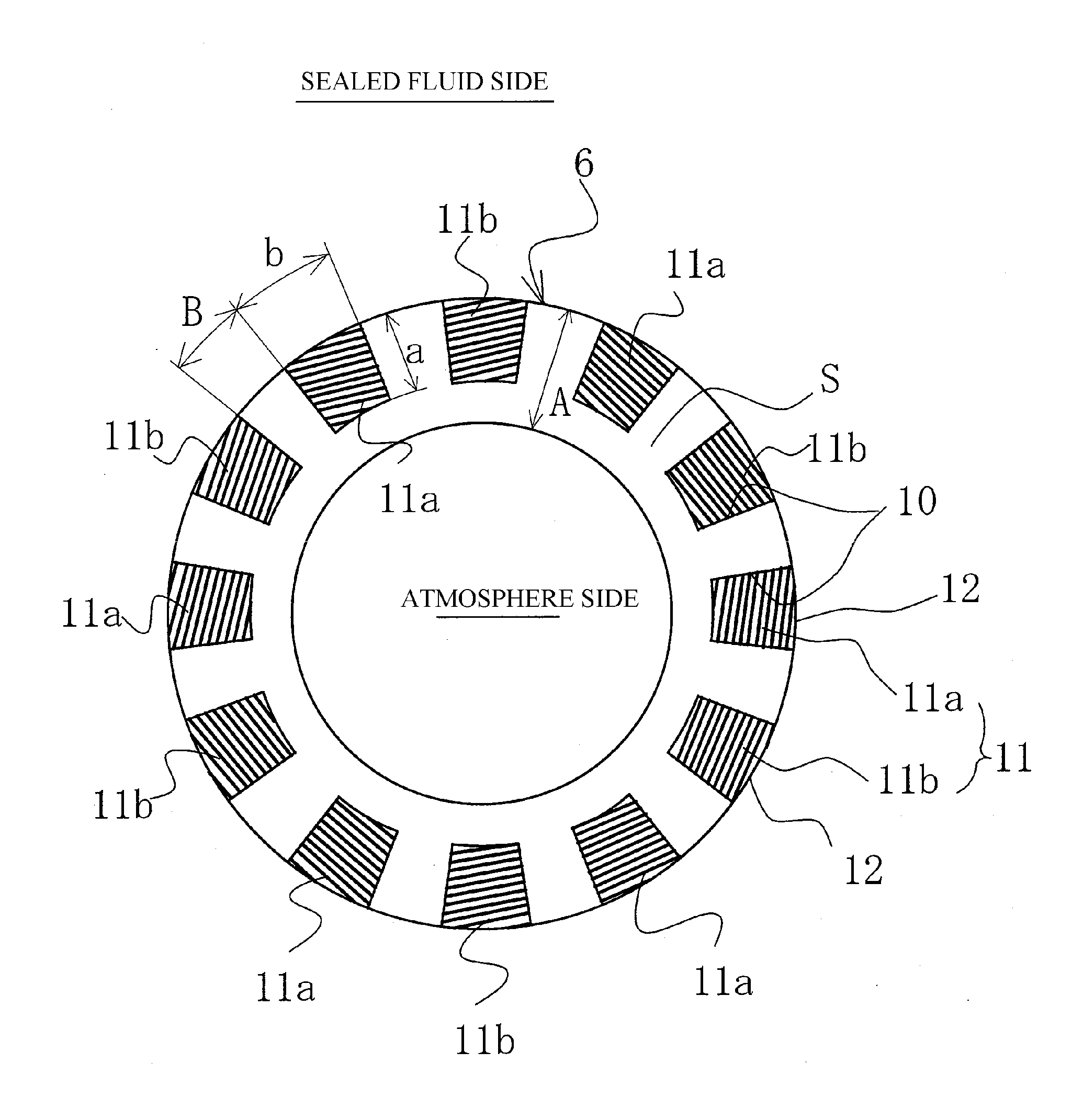
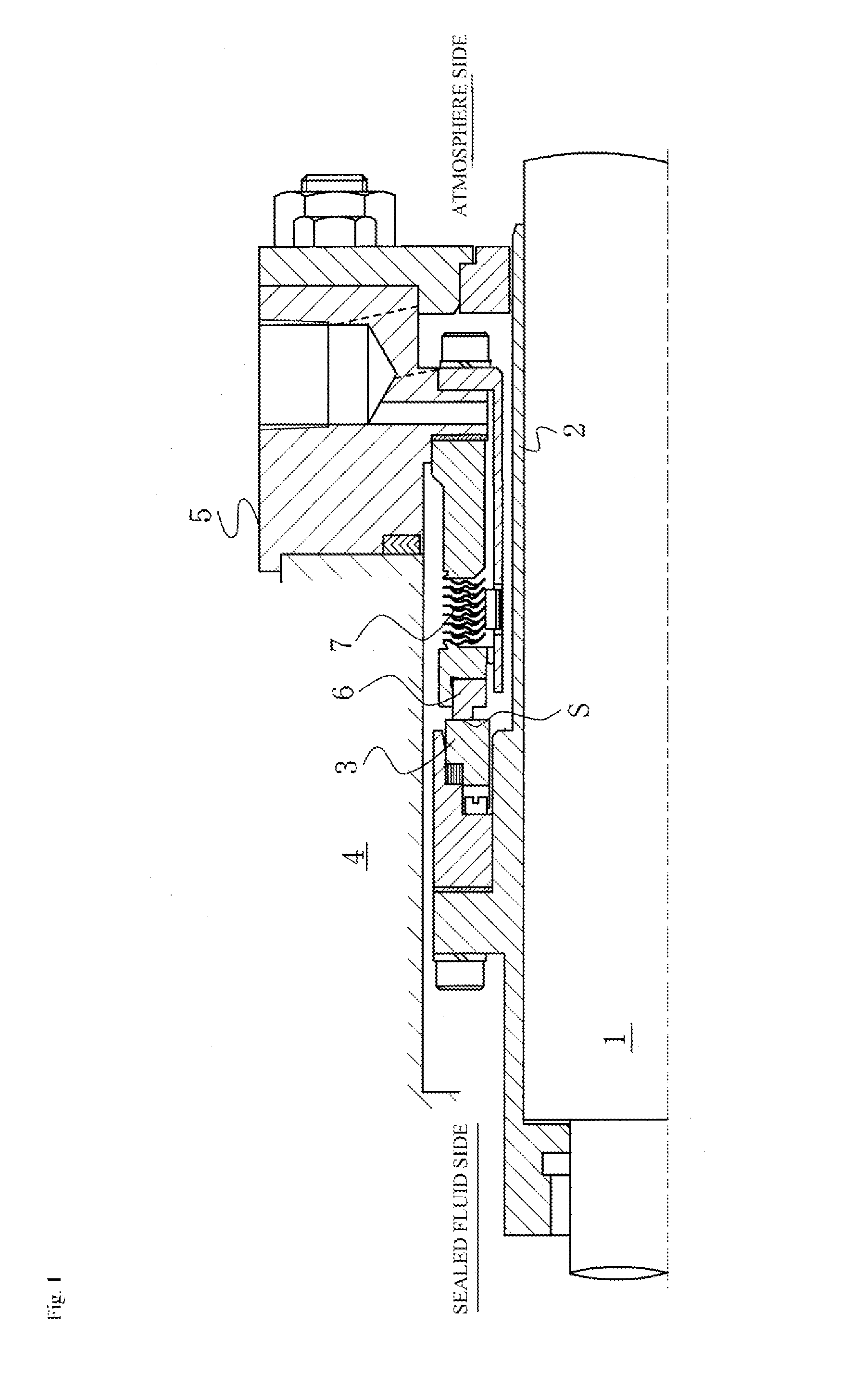
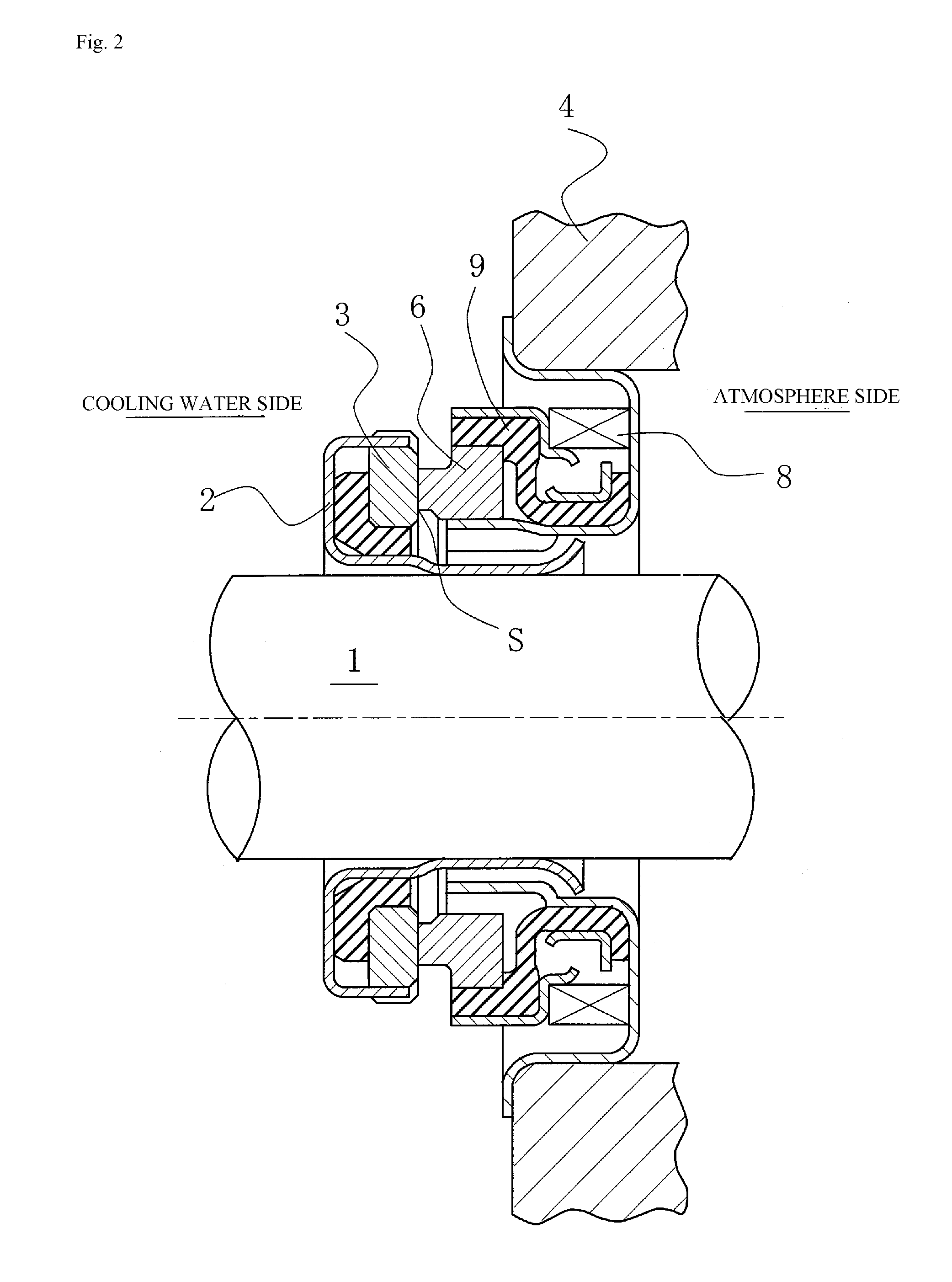
[0080]FIG. 3 is a plan view illustrating a mechanical seal as in a first embodiment of the present invention, as exemplified in FIGS. 1 and 2, wherein the first embodiment illustrates a case where sealed-fluid-accommodating blocks and pumping parts are formed on the sealing face S of the fixed ring 6, which, of the sealing faces of the fixed ring 6 and the rotating ring 3, has the lesser width in the radial direction.
[0081]In FIG. 3, a plurality of sealed-fluid-accommodating blocks 10 separated in the circumferential direction are formed on the sealing face S of the fixed ring 6 so as to be a part of the sealing face S in the radial direction and to communicate directly to a sealed fluid accommodation space via an outer peripheral side 12.
[0082]In the case of an outside-type mechanical seal, in which the sealed fluid side exists on the inside of the rotating ring 3 and the fixed ring 6, the sealed-fluid-accommodating blocks 10 may also be formed so as to be a part of the sealing fac...
second embodiment
[0111]FIG. 6 is a cross-sectional view illustrating the sealed-fluid-accommodating blocks 10 and pumping parts 11 formed on the sealing face S of the fixed ring 6 of the mechanical seal as in the second embodiment of the present invention, as exemplified in FIGS. 1 and 2.
[0112]In the first embodiment, the pumping parts 11 were formed to be parallel to a plane orthogonal to the shaft in the circumferential direction and the radial direction; however, in FIG. 6, the intake pumping parts 11a formed on the bottom part of the sealed-fluid-accommodating blocks 10 are formed so that the linear irregularities thereof gradually become higher toward the direction R of rotation of the rotating ring 3, which is an opposing sliding member; the discharge pumping parts 11b are formed so that the linear irregularities thereof gradually become lower toward the direction R of rotation of the rotating ring 3, which is an opposing sliding member.
[0113]In this manner, in addition to the slope with respe...
third embodiment
[0117]FIG. 7 is a plan view illustrating a mechanical seal as in a third embodiment of the present invention, as exemplified in FIGS. 1 and 2, wherein this embodiment is a case where the sealed-fluid-accommodating blocks and pumping parts are formed on the sealing face of the rotating ring, which, of the sealing faces of the fixed ring and the rotating ring, has the greater width in the radial direction.
[0118]In FIG. 7, the plurality of sealed-fluid-accommodating blocks 10 separated in the circumferential direction are formed on the sealing face S of the rotating ring 3, which, of the sealing faces of the rotating ring 3 and the fixed ring 6, has the greater sealing face width in the radial direction. The plurality of sealed-fluid-accommodating blocks 10 are formed on a part of the sealing face S that does not include the radial outward and inward sides thereof, and are formed so that a part of the sealed fluid side of the sealed-fluid-accommodating blocks 10 is not covered by the o...
PUM
 Abstract
Description
Claims
Application Information
 - R&D
- Intellectual Property
- Life Sciences
- Materials
- Tech Scout
- Unparalleled Data Quality
- Higher Quality Content
- 60% Fewer Hallucinations
Browse by: Latest US Patents, China's latest patents, Technical Efficacy Thesaurus, Application Domain, Technology Topic, Popular Technical Reports.
© 2025 PatSnap. All rights reserved.Legal|Privacy policy|Modern Slavery Act Transparency Statement|Sitemap|About US| Contact US: help@patsnap.com


