Endovascular electrolytically detachable wire and tip for the formation of thrombus in arteries, veins, aneurysms, vascular malformations and arteriovenous fistulas

a technology of electrolysis and endovascular electrolysis, which is applied in the field of endovascular electrothrombic formation of thrombosis in arteries, veins, aneurysms, and arteriovenous fistulas, can solve the problems of insufficient methodology, increased patient mortality from underlying disease, and increased risk of aneurysm ruptur

Inactive Publication Date: 2011-09-27
RGT UNIV OF CALIFORNIA
View PDF300 Cites 14 Cited by
  • Summary
  • Abstract
  • Description
  • Claims
  • Application Information

AI Technical Summary

Benefits of technology

[0023]In another embodiment, the guidewire and tip (or wire) are used within a microcatheter and in the step of detaching the distal tip from the guidewire (or wire), the guidewire and tip (or wire) are longitudinally displaced within the microcatheter. The microcatheter has radio-opaque proximal and tip markers. The guidewire and tip (or wire) have collectively a single radio-opaque marker. The displacement of the guidewire and tip (or wire) moves the single radio-opaque marker to the proximity of the proximal marker on the microcatheter. At this point the tip will be fully deployed in the vascular cavity and tip separation may proceed. It is not necessary then in this embodiment to be able to see actual deployment of the tip before separation. The tip marker allows and enhances direct observation of the correct placement of the catheter tip into the opening of the vascular cavity.
[0027]The invention is also a wire for use in formation of an occlusion within a vascular cavity used in combination with a microcatheter comprising a core wire, and a detachable elongate tip portion extending the core wire for a predetermined lineal extent. The tip portion is adapted to be packed into the vascular cavity to form the occlusion in the vascular cavity and coupled to the distal portion of the core wire. As a result, endovascular occlusion of the vascular cavity can be performed.
[0031]The invention is still further characterized as a microcatheter system for use in formation of an occlusion within a vascular cavity comprising a microcatheter having a distal end adapted for disposition in the proximity of the vascular cavity. The distal end has an electrode disposed thereon. A conductive guidewire is disposed in the microcatheter and longitudinally displaceable therein. The guidewire comprises a core wire, and an elongate tip portion extending the core wire for a predetermined lineal extent. The tip portion is adapted to be packed into the vascular cavity to form the occlusion in the vascular cavity. The tip portion is coupled to the distal portion of the core wire. The occlusion is formed by means of applying a current between the tip portion and the electrode on the microcatheter when the tip portion is disposed into the vascular cavity. As a result, endovascular occlusion of the vascular cavity can be performed.
[0038]The invention is also wire for use in formation of an occlusion within a vascular cavity used in combination with a microcatheter. The invention comprises a core wire and a detachable elongate tip portion extending the core wire for a predetermined lineal extent. The core wire is adapted to being packed into the vascular cavity to form the occlusion in the vascular cavity and is coupled to the distal portion of the core wire. The tip portion includes a first segment for disposition into the cavity and a second segment for coupling the first portion to the core wire. The second segment is adapted to be electrolysized upon application of current. An insulating coating is disposed on the first segment. The second segment is left exposed to permit selective electrolysis thereof. As a result, endovascular occlusion of the vascular cavity can be performed.

Problems solved by technology

Because of the mortality and morbidity rate expected, the surgical procedure is often delayed while waiting for the best surgical time with the result that an additional percentage of patients will die from the underlying disease or defect prior to surgery.
While endovascular balloon embolization of berry aneurysms is an attractive method in situations where an extravascular surgical approach is difficult, inflation of a balloon into the aneurysm carries some risk of aneurysm rupture due to possible over-distention of portions of the sac and due to the traction produced while detaching the balloon.
While remedial procedures exist for treating a ruptured aneurysm during classical extravascular surgery, no satisfactory methodology exists if the aneurysm breaks during an endovascular balloon embolization.
This may not lead to a satisfactory result and further increases the risk of rupture.
Still further, balloon embolization is not always possible.
If the diameter of the deflated balloon is too great to enter the intracerebral arteries, especially in the cases where there is a vasospasm, complications with ruptured intracranial aneurysms may occur.
The procedure then must be deferred until the spasm is resolved and this then incurs a risk of rebleeding.
However, each of these techniques involves some type of intrusive procedure to approach the aneurysm from the exterior of the body.
In addition to the risks caused by temporary blockage of the parent artery, the risks of seepage of such a polymerizing adhesive into the parent artery exists, if it is not completely blocked with consequent occlusion of the artery.
The success of this procedure involves exposing the aneurysm sufficiently to allow air gun injection and has not been convincingly shown as successful for thrombic formations.
This treatment has not been entirely successful because of the risk of fragmentation of the metallic thrombus when the extravascular magnet is removed.
The treatment has not been favored, because of the need to puncture the aneurysm, the risk of occlusion of the parent artery, the use of unusual and expensive equipment, the need for a craniectomy and general anesthesia, and the necessity to penetrate cerebral tissue to reach the aneurysm.
In addition, the hot melt adhesive attaching the tip to the optic fiber melts and is dispersed into the adjacent blood tissue where it resolidifies to form free particles within the intracranial blood stream with much the same disadvantages which result from fragmentation of a ferromagnetic electrothrombosis.

Method used


Image

  • Endovascular electrolytically detachable wire and tip for the formation of thrombus in arteries, veins, aneurysms, vascular malformations and arteriovenous fistulas
  • Endovascular electrolytically detachable wire and tip for the formation of thrombus in arteries, veins, aneurysms, vascular malformations and arteriovenous fistulas
  • Endovascular electrolytically detachable wire and tip for the formation of thrombus in arteries, veins, aneurysms, vascular malformations and arteriovenous fistulas

Examples


first embodiment

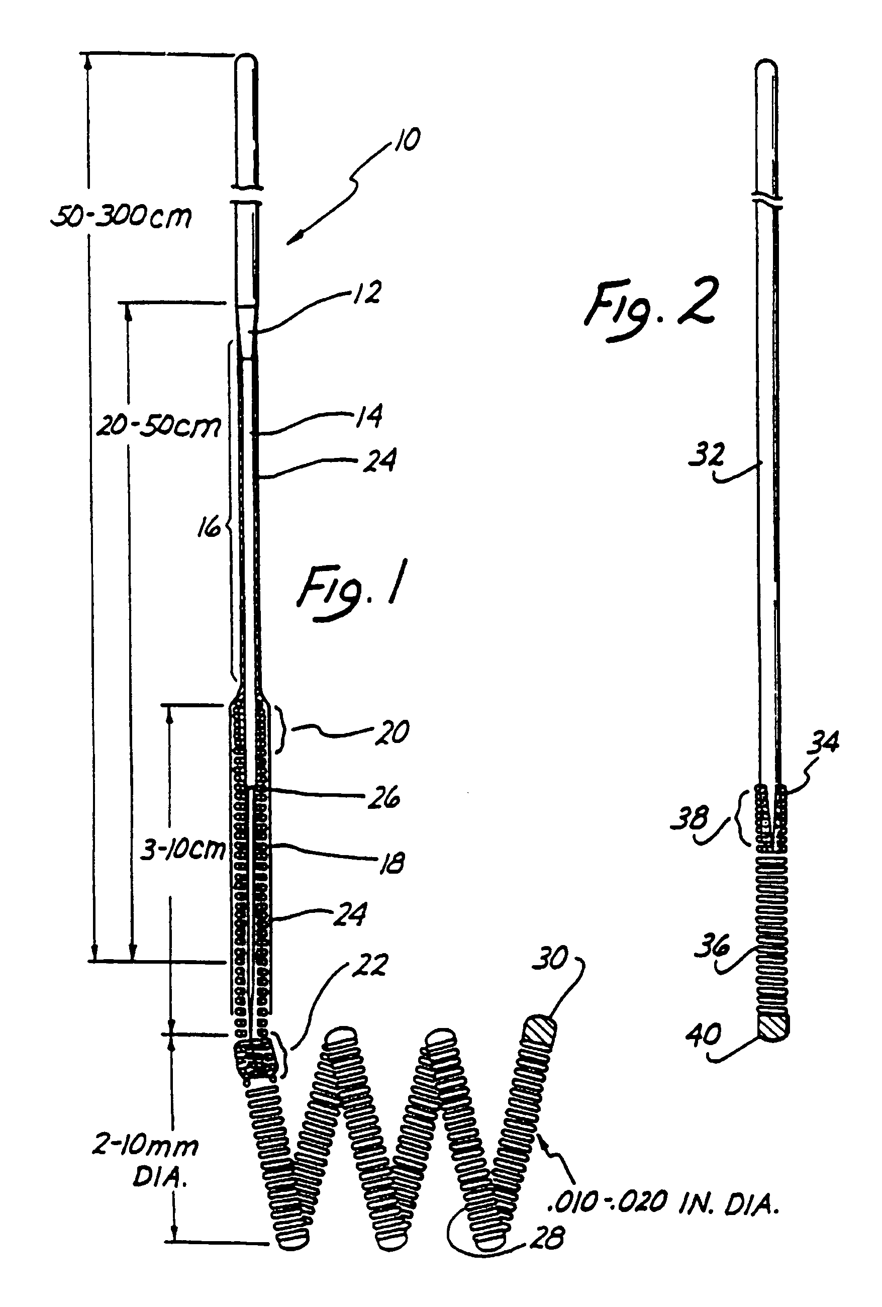
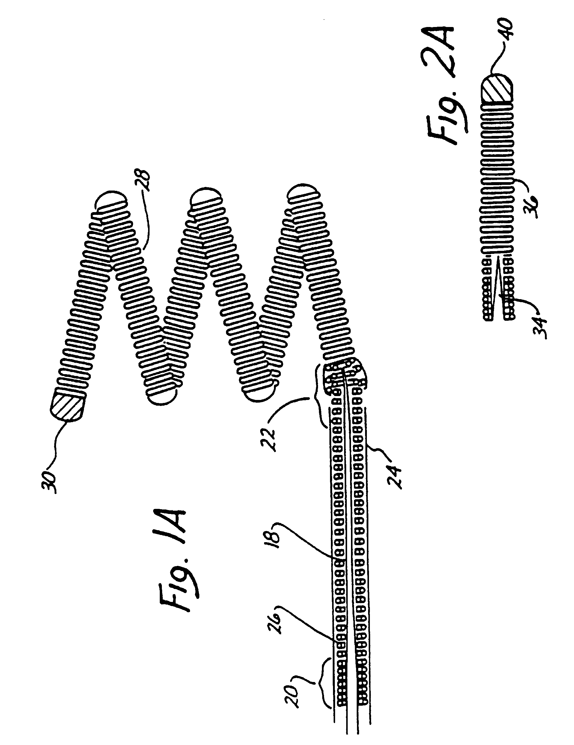
[0051]FIG. 1 is an enlarged side view of the distal end of the wire and tip shown in partial cross-sectional view. A conventional Teflon laminated or similarly insulated stainless steel wire 10 is disposed within a protective nicrocatheter (not shown). Stainless steel wire 10 is approximately 0.010-0.020 inch (0.254-0.508 mm) in diameter. In the illustrated embodiment, wire 10 is tapered at its distal end to form a conical section 12 which joins a section 14 of reduced diameter which extends longitudinally along a length 16 of wire 10. Section 16 then narrows gradually down to a thin threadlike portion 18 beginning at a first bonding location 20 and ending at a second bonding location 22.

[0052]The stainless steel wire 10, comprised of that portion disposed within the microcatheter body, tapered section 12, reduced diameter section 16 and threadlike section 18, is collectively referred to as a core wire which typically is 50-300 cm. in length.

[0053]In the illustrated embodiment the p...

third embodiment

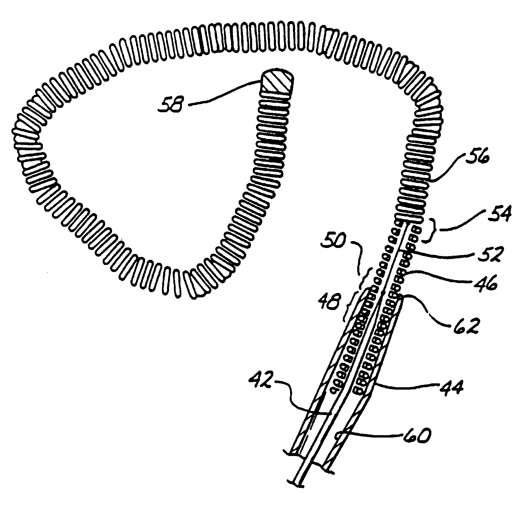
[0059]As will be described below in greater detail in connection with FIG. 3, after placement of secondary coil 28 within the interior of the aneurysm, a direct current is applied to wire 10 from a voltage source exterior to the body. The positive charge on secondary coil 28 within the cavity of the aneurysm causes a thrombus to form within the aneurysm by electrothrombosis. Detachment of the tip occurs either: (1) by continued application of current for a predetermined time when the portion 18 is exposed to blood; or (2) by movement of the wire to expose portion 18 to blood followed by continued current application for a predetermined time. Ultimately, both threadlike portion and stainless steel coil 26 will be completely disintegrated at least at one point, thereby allowing wire 10 to be withdrawn from the vascular space while leaving secondary coil 28 embedded within the thrombus formed within the aneurysm.

second embodiment

[0060]FIG. 2 illustrates in enlarged partially cross-sectional view the invention. Stainless steel core 32 terminates in a conical distal portion 34. Stainless steel coil 36, shown in cross-sectional view, is soldered to distal portion 34 of wire 32 at bonding location 38. The opposing end of the stainless steel coil 36 is provided with a soldered, rounded platinum tip 40. In the illustrated embodiment, stainless steel core wire 32 is approximately 0.010 inch in diameter with the length of stainless steel coil 36 being approximately 8 cm. with the longitudinal length of platinum tip 40 being between 3 and 10 mm. The total length of wire 32 from tip 40 to the proximate end is approximately 150 cm.

[0061]The embodiment of FIG. 2 is utilized in exactly the same manner as described above in connection with FIG. 1 to form a thrombic mass within an aneurysm or other vascular cavity. The embodiment of FIG. 2 is distinguished from that shown in FIG. 1 by the absence of the extension of stain...


PUM


Abstract

An artery, vein, aneurysm, vascular malformation or arterial fistula is occluded through endovascular occlusion by the endovascular insertion of a platinum wire and / or tip into the vascular cavity. The vascular cavity is packed with the tip to obstruct blood flow or access of blood in the cavity such that the blood clots in the cavity and an occlusion if formed. The tip may be elongate and flexible so that it packs the cavity by being folded upon itself a multiple number of times, or may pack the cavity by virtue of a filamentary or fuzzy structure of the tip. The tip is then separated from the wire mechanically or by electrolytic separation of the tip from the wire. The wire and the microcatheter are thereafter removed leaving the tip embedded in the thrombus formed within the vascular cavity. Movement of wire in the microcatheter is more easily tracked by providing a radioopaque proximal marker on the microcatheter and a corresponding indicator marker on the wire. Electrothrombosis is facilitate by placing the ground electrode on the distal end of the microcatheter and flowing current between the microcatheter electrode and the tip.

Description

[0001]This application is a continuation of application Ser. No. 08 / 801,795 filed Feb. 14, 1997, issued as U.S. Pat. No. 5,855,578, which in turn wasis a continuation of application Ser. No. 08 / 485,821, filed Jun. 6, 1995, now abandoned, which is a divisional of application Ser. No. 08 / 311,508, filed on Sep. 23, 1994, issued as U.S. Pat. No. 5,540,680, which is a continuation application of application Ser. No. 07 / 840,211 filed on Feb. 24, 1992, issued as U.S. Pat. No. 5,354,295, and which in its turn wasis a continuation-in-part application of application Ser. No. 07 / 492,717, filed Mar. 13, 1990, issued as U.S. Pat. No. 5,122,136.BACKGROUND OF THE INVENTION[0002]1. Field of the Invention[0003]The invention relates to a method and apparatus for endovascular electrothrombic formation of thrombi in arteries, veins, aneurysms, vascular malformations and arteriovenous fistulas.[0004]2. Description of the Prior Art[0005]Approximately 25,000 intracranial aneurysms rupture every year in No...

Claims


Application Information

Patent Timeline
Patent Type & Authority Patents(United States)
IPC IPC(8): A61B17/00A61B18/08A61B17/12A61B18/12A61B18/14A61B19/00
CPCA61B17/12022A61B17/12113A61B17/1214A61B17/12145A61B17/1215A61B17/12172A61B18/1402A61B18/1492A61B2017/00292A61B2017/12054A61B2017/12063A61B2017/12095A61B2017/22038A61B2018/00678A61B2018/00761A61B2018/00875A61B2018/00886A61B2018/1226A61B2018/1253A61B2018/126A61B2018/1266A61B2018/1435A61B2018/1495A61M25/09A61M2025/09175A61B90/39A61B2090/3966
Inventor GUGLIELMI, GUIDOSEPETKA, IVAN
Owner RGT UNIV OF CALIFORNIA
Why Eureka
Try Eureka