Endovascular electrolytically detachable wire and tip for the formation of thrombus in arteries, veins, aneurysms, vascular malformations and arteriovenous fistulas
- Summary
- Abstract
- Description
- Claims
- Application Information
AI Technical Summary
Benefits of technology
Problems solved by technology
Method used
Image
Examples
first embodiment
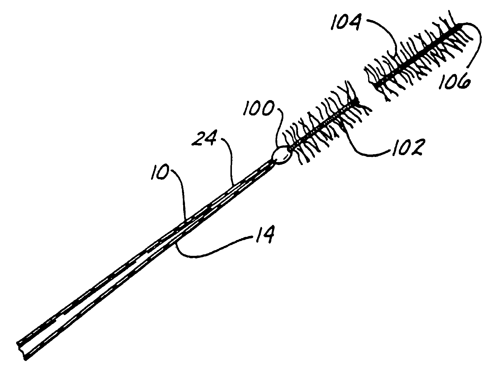
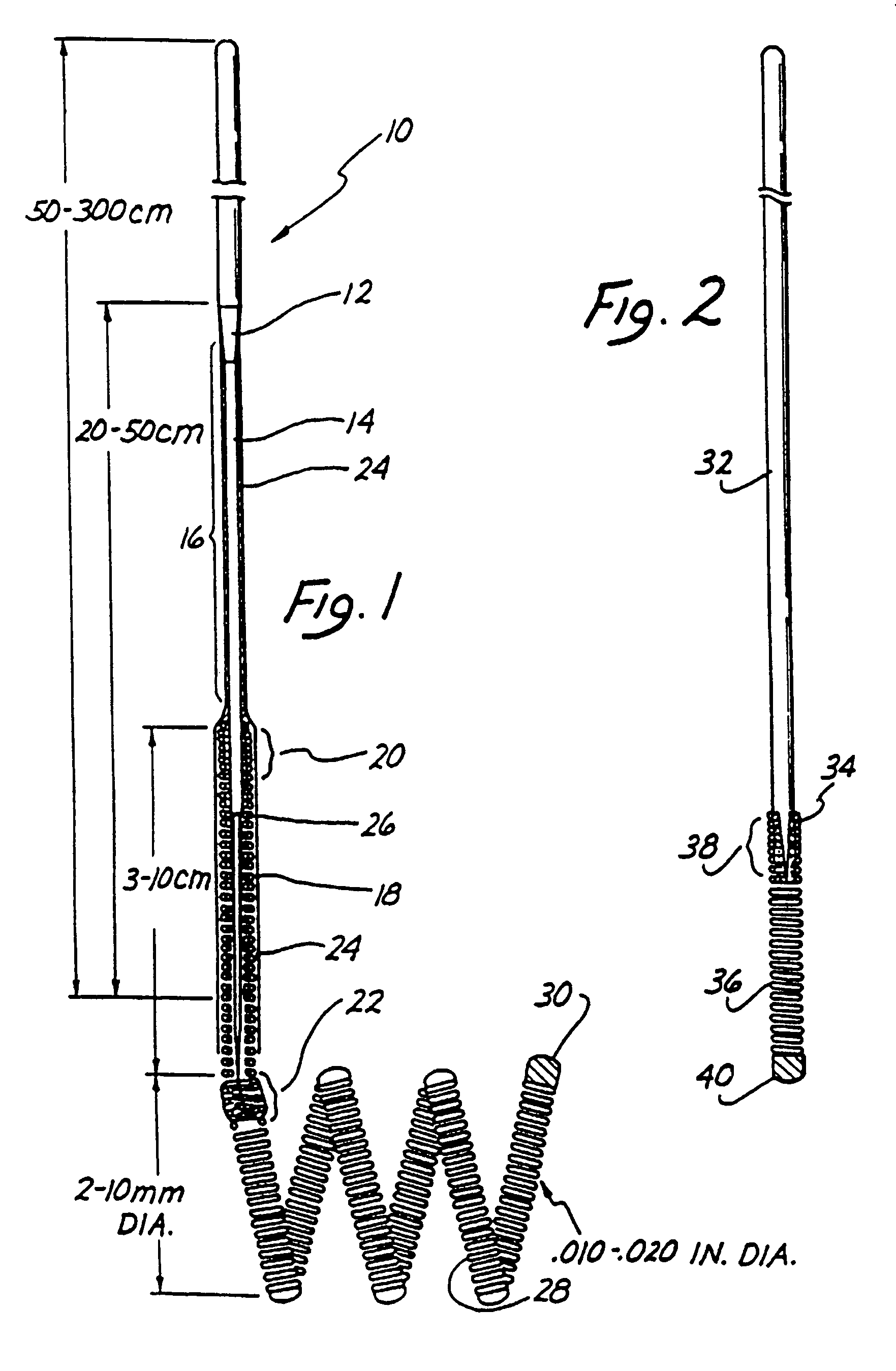
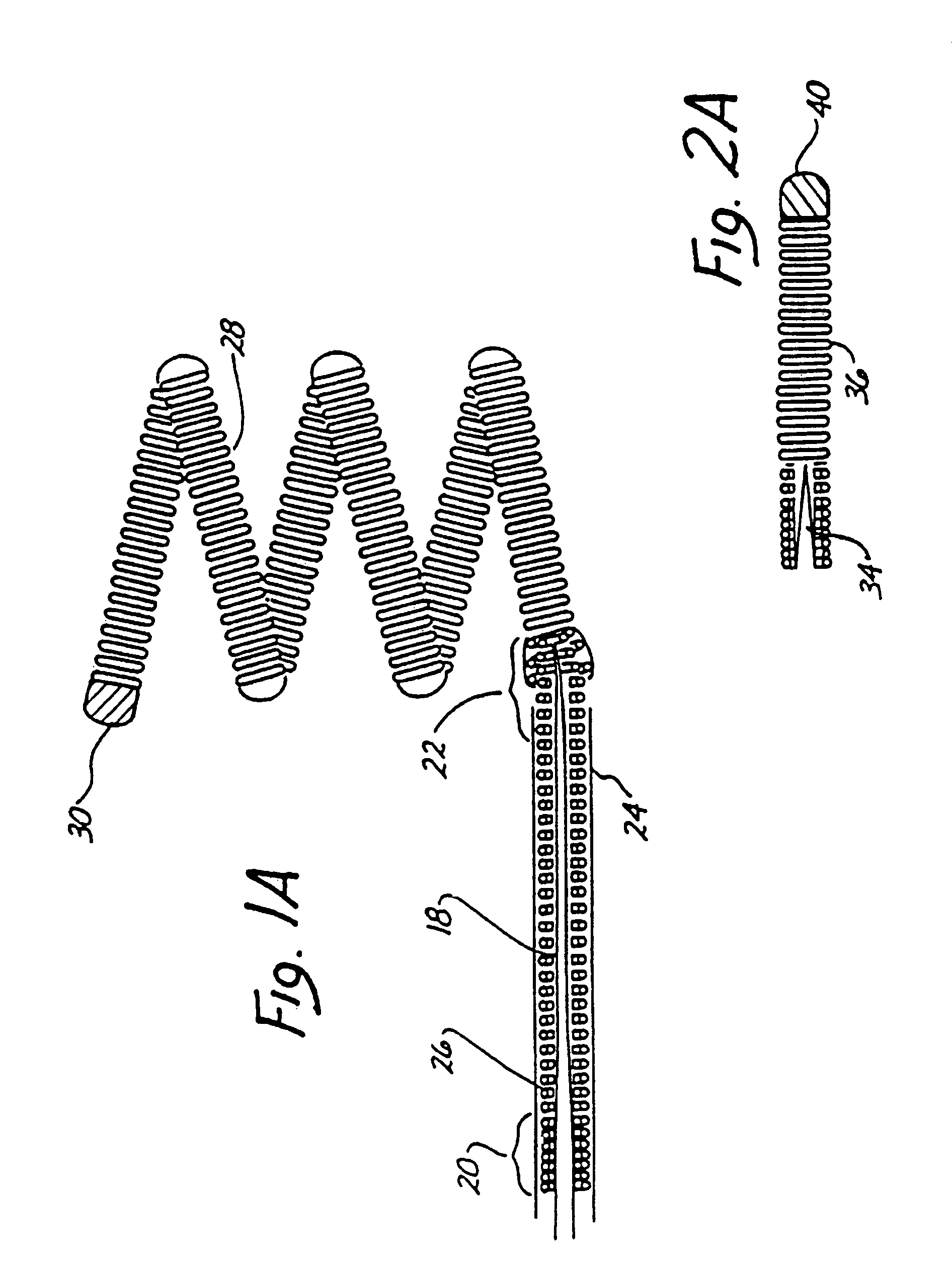
FIG. 1 is an enlarged side view of the distal end of the wire and tip shown in partial cross-sectional view. A conventional Teflon laminated or similarly insulated stainless steel wire 10 is disposed within a protective microcatheter (not shown). Stainless steel wire 10 is approximately 0.010-0.020 inch (0.254-0.508 mm) in diameter. In the illustrated embodiment, wire 10 is tapered at its distal end to form a conical section 12 which joins a section 14 of reduced diameter which extends longitudinally along a length 16 of wire 10. Section 16 then narrows gradually down to a thin threadlike portion 18 beginning at a first bonding location 20 and ending at a second bonding location 22.
The stainless steel wire 10, comprised of that portion disposed within the microcatheter body, tapered section 12, reduced diameter section 16 and threadlike section 18, is collectively referred to as a core wire which typically is 50-300 cm. in length.
In the illustrated embodiment the portion of the core...
third embodiment
As will be described below in greater detail in connection with FIG. 3, after placement of secondary coil 28 within the interior of the aneurysm, a direct current is applied to wire 10 from a voltage source exterior to the body. The positive charge on secondary coil 28 within the cavity of the aneurysm causes a thrombus to form within the aneurysm by electrothrombosis. Detachment of the tip occurs either: (1) by continued application of current for a predetermined time when the portion 18 is exposed to blood; or (2) by movement of the wire to expose portion 18 to blood followed by continued current application for a predetermined time. Ultimately, both threadlike portion and stainless steel coil 26 will be completely disintegrated at least at one point, thereby allowing wire 10 to be withdrawn from the vascular space while leaving secondary coil 28 embedded within the thrombus formed within the aneurysm.
second embodiment
FIG. 2 illustrates in enlarged partially cross-sectional view the invention. Stainless steel core 32 terminates in a conical distal portion 34. Stainless steel coil 36, shown in cross-sectional view, is soldered to distal portion 34 of wire 32 at bonding location 38. The opposing end of the stainless steel coil 36 is provided with a soldered, rounded platinum tip 40. In the illustrated embodiment, stainless steel core wire 32 is approximately 0.010 inch in diameter with the length of stainless steel coil 36 being approximately 8 cm. with the longitudinal length of platinum tip 40 being between 3 and 10 mm. The total length of wire 32 from tip 40 to the proximate end is approximately 150 cm.
The embodiment of FIG. 2 is utilzed in exactly the same manner as described above in connection with FIG. 1 to form a thrombic mass within an aneurysm or other vascular cavity. The embodiment of FIG. 2 is distinguished from that shown in FIG. 1 by the absence of the extension of stainless core 32 ...
PUM
 Abstract
Description
Claims
Application Information
 - R&D
- Intellectual Property
- Life Sciences
- Materials
- Tech Scout
- Unparalleled Data Quality
- Higher Quality Content
- 60% Fewer Hallucinations
Browse by: Latest US Patents, China's latest patents, Technical Efficacy Thesaurus, Application Domain, Technology Topic, Popular Technical Reports.
© 2025 PatSnap. All rights reserved.Legal|Privacy policy|Modern Slavery Act Transparency Statement|Sitemap|About US| Contact US: help@patsnap.com


