Magnetic bearing control system of accurately compensating magnetic suspension control torque gyroscope support rigidity

A technology for controlling moment gyro and support stiffness, applied in the field of magnetic bearing stiffness, can solve problems such as disturbance, poor compensation accuracy, and system instability, to eliminate compensation errors, overcome poor accuracy, and improve torque output accuracy and response speed Effect

Inactive Publication Date: 2007-09-05
BEIHANG UNIV
View PDF3 Cites 0 Cited by
  • Summary
  • Abstract
  • Description
  • Claims
  • Application Information

AI Technical Summary

Problems solved by technology

However, on the one hand, the actual system usually adopts PID control, and the differential coefficient is not allowed to be very large due to the restriction of the noise level. If the stiffness is too high, the system damping will be reduced, resulting in system instability; on the other hand, there is a certain Even if the high stiffness of fixed parameters is still in the stable range, it is difficult to adapt to the changing frame angular rate and cause disturbance, so the compensation accuracy is poor

Method used


Image

  • Magnetic bearing control system of accurately compensating magnetic suspension control torque gyroscope support rigidity
  • Magnetic bearing control system of accurately compensating magnetic suspension control torque gyroscope support rigidity
  • Magnetic bearing control system of accurately compensating magnetic suspension control torque gyroscope support rigidity

Examples


Embodiment Construction

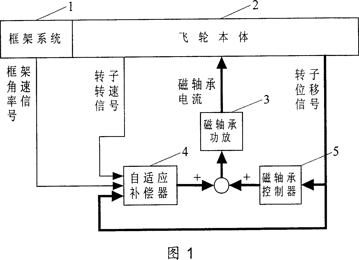
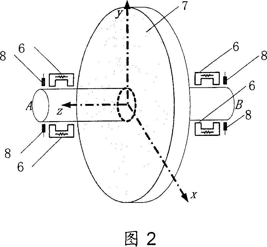
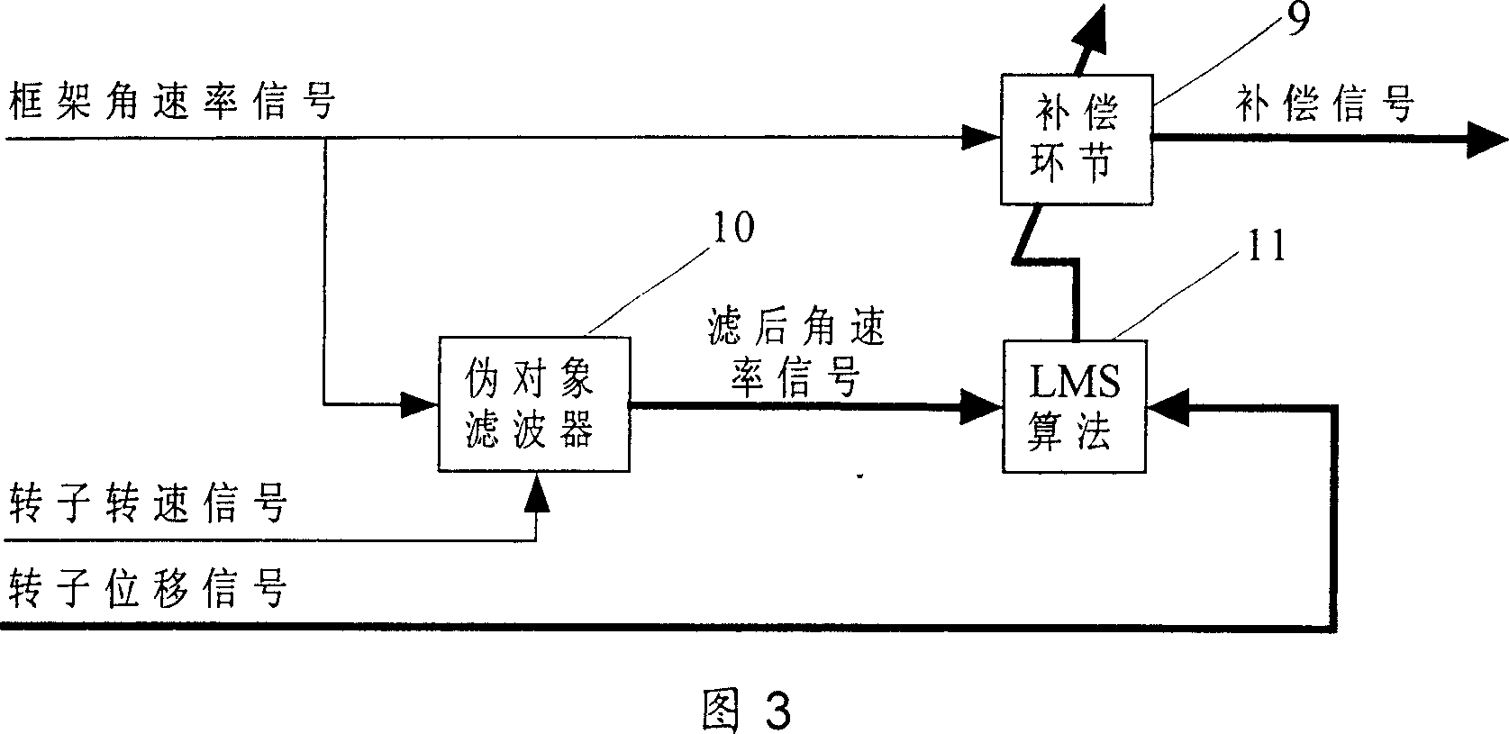
[0014]As shown in Figure 1, the present invention mainly includes a flywheel body 2, a magnetic bearing power amplifier 3, and a magnetic bearing controller 5. The flywheel body 2 is composed of a magnetic bearing electromagnet 6, a rotor 7, a displacement sensor 8 and a rotor drive system. For CMG, it also needs a frame drive system, as a device to drive the frame to achieve a given angular rate, and at the same time output the frame angular rate signal required by the magnetic levitation control system; for the flywheel body 2, a rotor motor drive system is also required, As a device to drive the rotor 7 to reach the rated speed, it also outputs the rotor speed signal required by the magnetic levitation control system. The rotor displacement signal is connected to the controller 5, and the control signal is output after calculation; the frame angular rate signal, the rotor speed signal and the rotor displacement signal are connected to the adaptive compensator 4 at the same time...


PUM


Abstract

The disclosed control system includes flywheel body, power amplifier for magnetic bearing, controller for magnetic bearing and adaptive compensator. Through collecting signals including angular rate of frame, speed of rotor, and displacement of rotor, the adaptive compensator carries out adaptive compensation calculation. Sum of calculated compensation quantity and the output of controller for magnetic bearing is connected to the power amplifier for magnetic bearing in order to eliminate disturbing moment on rotor of magnetic suspension caused by moving frame. The invention lowers displacement of rotor caused by rotation of frame, raises response speed and precision of angular rate of frame, and improves response speed and precision of moment output of magnetic suspension control moment.

Description

Technical field [0001] The invention relates to a magnetic levitation control system, which can be used for accurately compensating the rigidity of the magnetic bearing when the magnetic levitation control moment gyroscope (Control Moment Gyroscope-CMG) frame rotates. Background technique [0002] The control moment gyroscope (CMG) is a key actuator necessary for the attitude control of large spacecraft such as space stations. CMG is composed of a high-speed rotor system and a frame servo system. The frame system forces the high-speed rotor to precess, and outputs gyro torque for adjusting the attitude of the spacecraft. High-speed rotor support is a key component of CMG. There are usually two ways of mechanical ball bearing support and magnetic bearing support. The corresponding CMG is called mechanical CMG and magnetic suspension CMG. Existing CMGs all use mechanical supports, and friction and wear in the mechanical supports will affect the reliability and service life of the C...

Claims


Application Information

Patent Timeline
Patent Type & Authority Patents(China)
IPC IPC(8): H02K7/09H02N15/00F16C32/04
Inventor 魏彤房建成陈冬于灵慧张鹏波
Owner BEIHANG UNIV
Why Eureka
Try Eureka