
Patsnap Eureka
For R&D, Patsnap Eureka makes reading and utilizing patents & technical documents easy.
Patsnap Eureka AIR
Designed for self-driven R&D workflows. Generate viable solutions, solve complex R&D challenges, empower your innovation with AI.

Patsnap Eureka Materials
Designed for material experts only. Revolutionize your material R&D, from search, analyze, to developing new materials.

TechResearch
Generate reliable direction feasibility study reports for your R&D in just a few steps.

TechSeek
Discover and master advanced knowledge NOW. Basics, ideas, possibilities, all at once.

TechMind
As an expert in R&D Theories, TechMind can generates customized viable solutions instantly.

TechRisk
Analyze your overall solution with one click, know your potential R&D risks in advance.

TechMonitor
Get weekly tech updates, stay abreast of the latest tech innovations and key insights.
Driving device capable of switching speed reduction ratio
A technology of transmission device and reduction ratio, which is applied in the direction of transmission device, transmission device control, and components with teeth, etc., which can solve the problems of large space and unfavorable miniaturization of scanning device
- Summary
- Abstract
- Description
- Claims
- Application Information
AI Technical Summary
Problems solved by technology
Method used
Image

Examples
Embodiment Construction
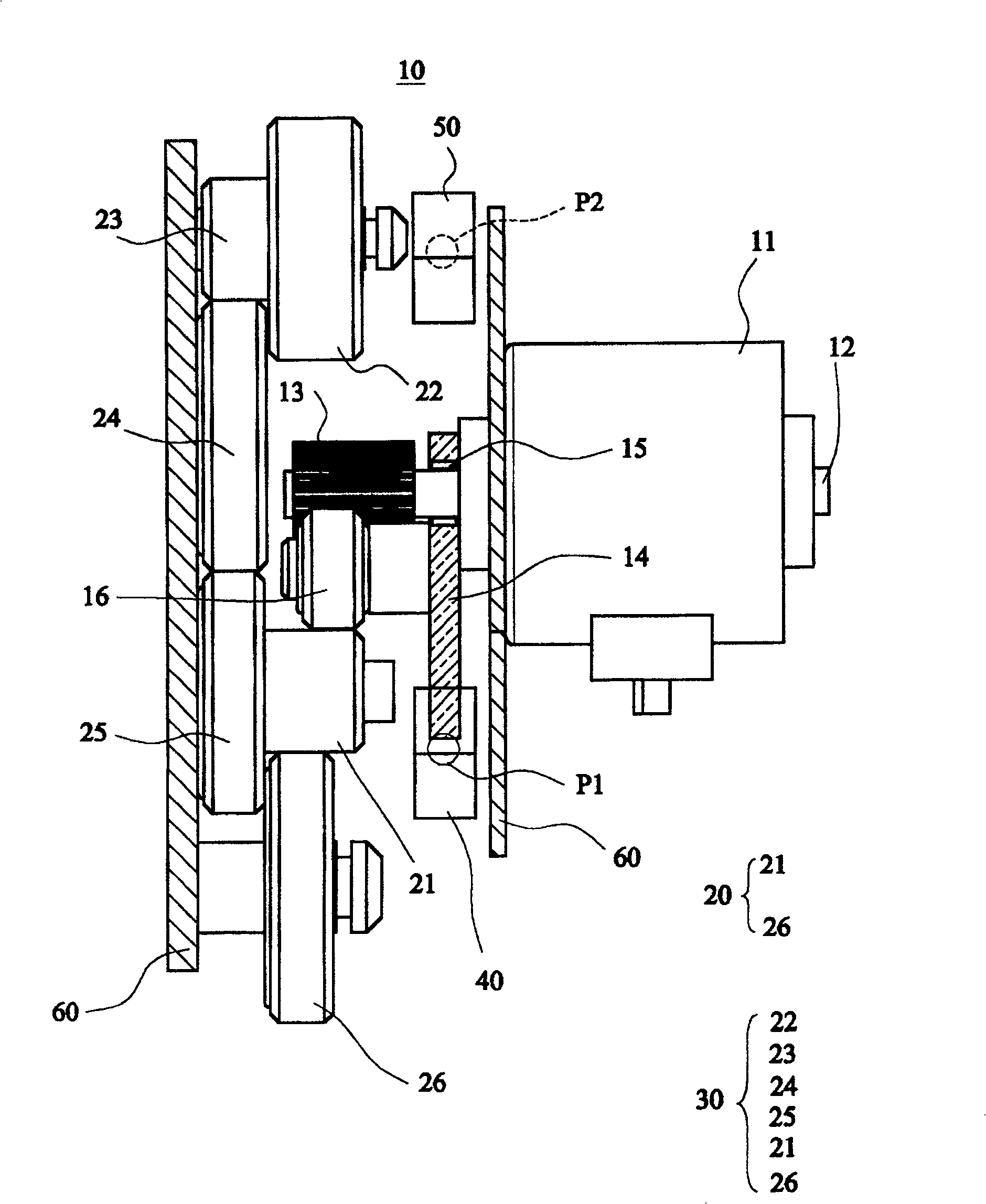
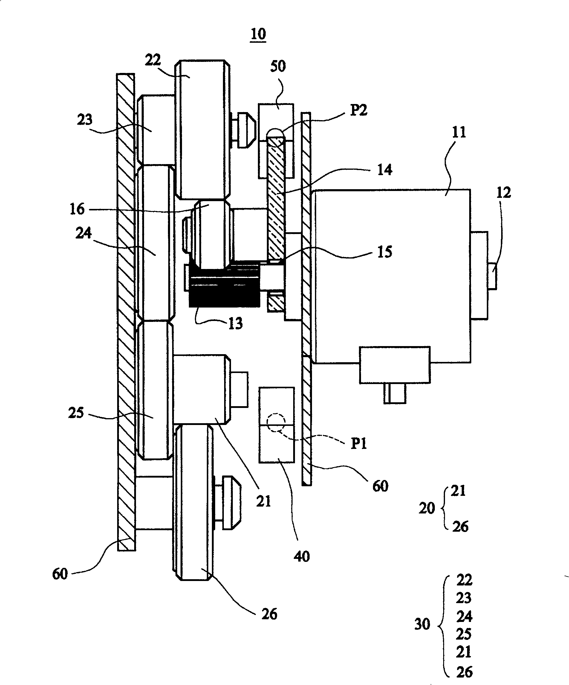
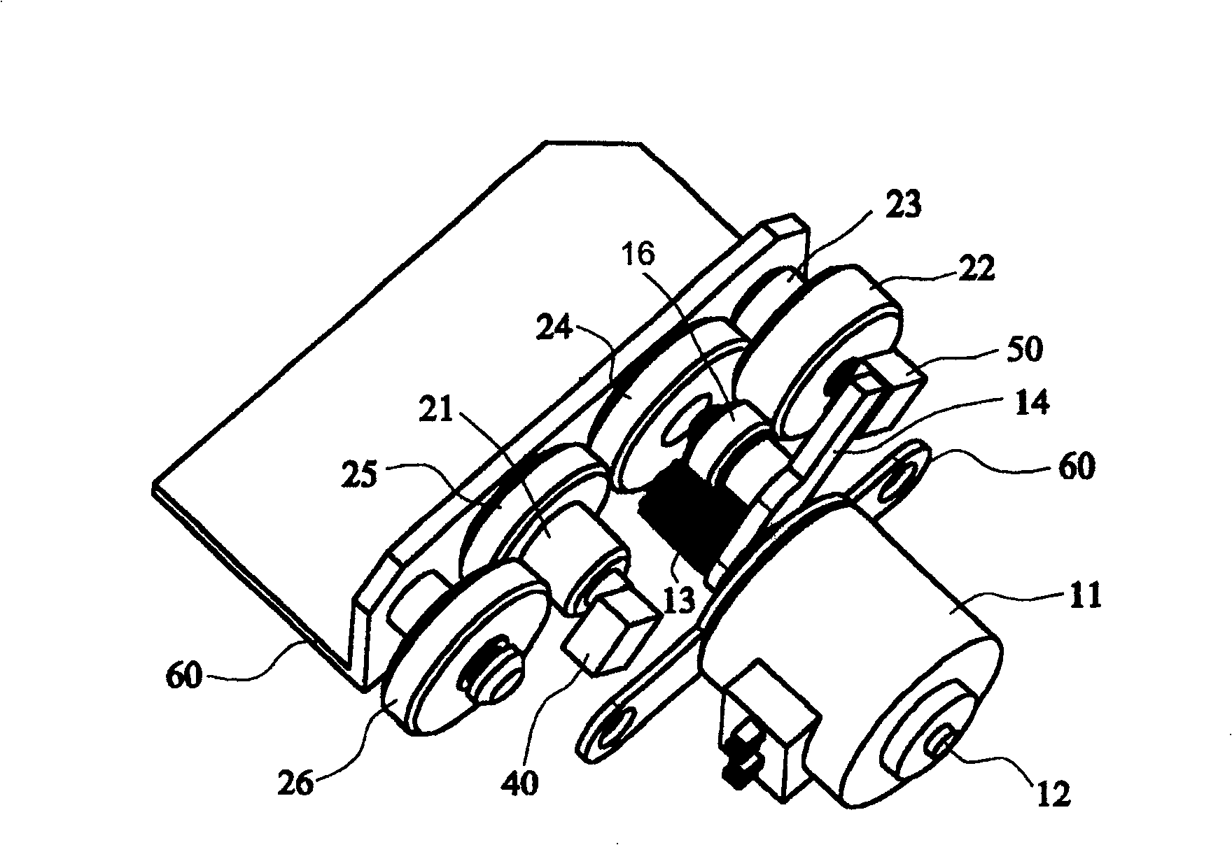
[0015] figure 1 and figure 2 The top schematic diagrams of the transmission device with switchable reduction ratio according to the first embodiment of the present invention in high-speed and low-speed states are respectively shown. image 3 show figure 2 3D schematic diagram of . Figure 4 show figure 2 Schematic diagram of the swing arm. Such as Figure 1 to Figure 4 As shown, the transmission device 10 with switchable reduction ratio of the present embodiment includes a motor 11, a driving gear 13, a swing arm 14, a swing arm gear 16, a first gear set 20, a second gear set 30, a first magnetic assembly 40 and The second magnetic assembly 50 . The motor 11 is fixed on the base 60 and has an output shaft 12 . The driving gear 13 is fixed on the output rotating shaft 12 . The swing arm 14 is pivotally connected to the output shaft 12 via an electromagnetic clutch 15 . The swing arm gear 16 is driven to rotate by the driving gear 13 and is mounted on the swing arm 1...
PUM
 Abstract
Description
Claims
Application Information
 - R&D Engineer
- R&D Manager
- IP Professional
- Industry Leading Data Capabilities
- Powerful AI technology
- Patent DNA Extraction
Browse by: Latest US Patents, China's latest patents, Technical Efficacy Thesaurus, Application Domain, Technology Topic, Popular Technical Reports.
© 2024 PatSnap. All rights reserved.Legal|Privacy policy|Modern Slavery Act Transparency Statement|Sitemap|About US| Contact US: help@patsnap.com