
Driving device capable of switching speed reduction ratio

A technology of transmission and reduction ratio, which is applied in the direction of transmission, transmission control, and components with teeth, etc., which can solve the problems of large space and unfavorable miniaturization of scanning devices

Inactive Publication Date: 2006-01-25
AVISION PRECISION IND (SUZHOU) CO LTD
View PDF0 Cites 0 Cited by
  • Summary
  • Abstract
  • Description
  • Claims
  • Application Information

AI Technical Summary

Problems solved by technology

However, adding a group of motors or power drives takes up a lot of space in the scanning device, which is not conducive to the miniaturization of the current scanning device

Method used


Image

  • Driving device capable of switching speed reduction ratio
  • Driving device capable of switching speed reduction ratio
  • Driving device capable of switching speed reduction ratio

Examples


no. 1 example

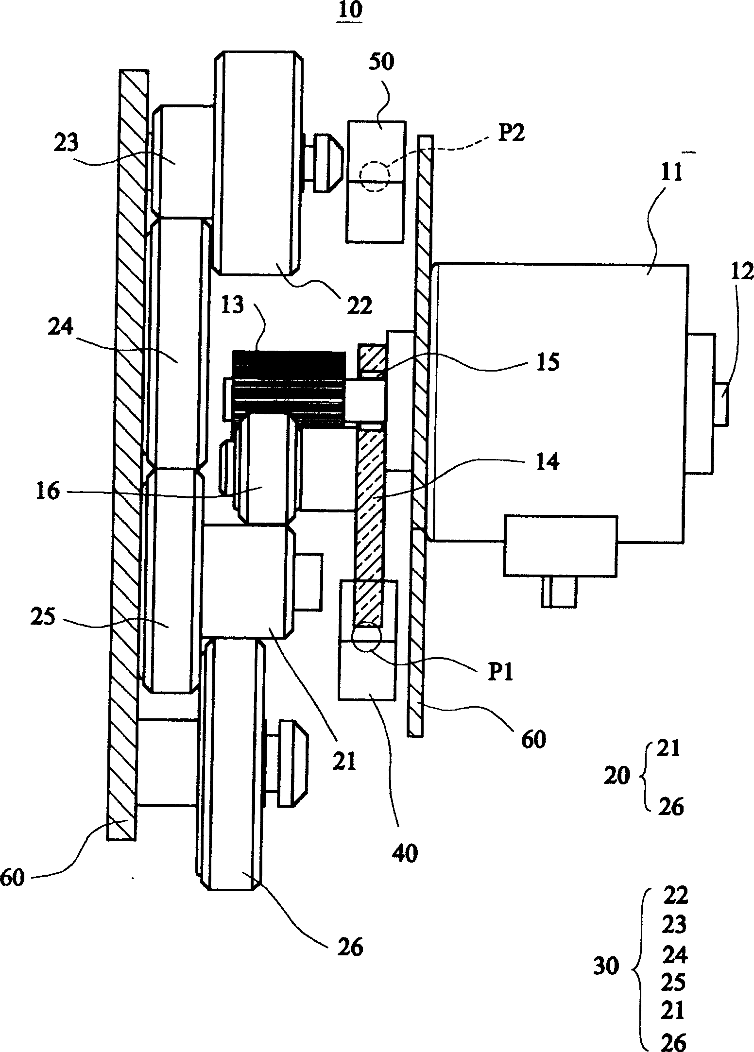
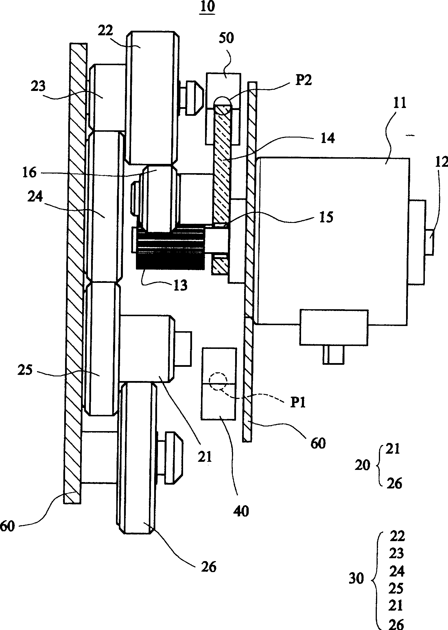
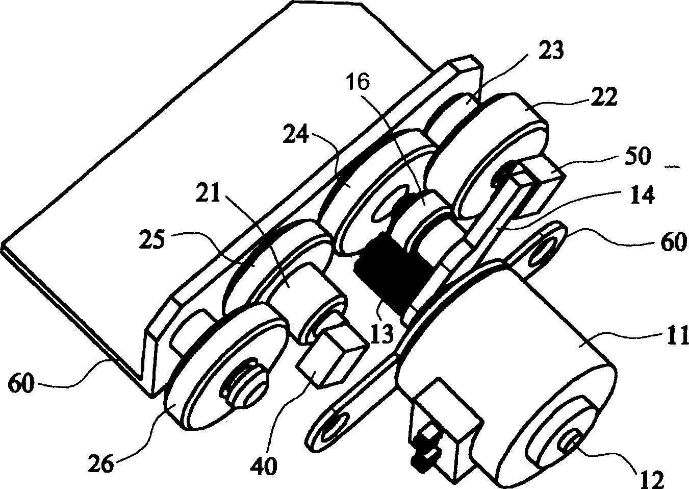
[0022] Figure 5 A schematic top view showing a transmission device with a switchable reduction ratio in a high-speed state according to the second embodiment of the present invention. Such as Figure 5 As shown, the transmission device 10 with switchable reduction ratio of this embodiment includes a motor 11, a driving gear 13, a swing arm 14', a swing arm gear 16, a first gear set 20, a second gear set 30, and a first solenoid valve 41 And the second solenoid valve 51. Some of the above-mentioned components are similar to the first embodiment, so only the differences from the first embodiment will be described below.

[0023] Different from the first embodiment, the swing arm 14' is directly pivoted on the output shaft 12. The first solenoid valve 41 is used to attract the swing arm 14' at the first position P1. The second solenoid valve 51 is used to attract the swing arm 14' at the second position P2. Therefore, this embodiment uses the action principle of the planeta...


PUM


Abstract

The invention is a switch reduction ratio driver, where a drive gear is fixed on the output rotating shaft of a motor, a rocker arm is hinged on the output rotating shaft by electromagnetic clutch, the rocker arm gear installed on the rocker arm is driven by the drive gear to rotate, the first gear group is driven by the rocker arm gear to rotate as the rocker arm is in the first position, the second gear group is driven by the rocker arm gear to rotate as the rocker arm is in the second position, and the first and second gear groups have different output speeds. Besides, the first magnetic component is used to absorb the rocker arm in the first position and the second magnetic component is used to absorb the rocker arm in the second position. Thus, it can switch the reduction ratios by the actions of the electromagnetic clutch and magnetic components.

Description

technical field [0001] The invention relates to a transmission device with a switchable reduction ratio, in particular to a transmission device which is applied in a scanning device and uses a magnetic component and a planetary gear mechanism to achieve a switchable reduction ratio. Background technique [0002] In a traditional flatbed scanning device, the scanning module is driven by a driving device to move back and forth. Generally, when scanning documents, the scanning module moves relatively slowly, but the scanning module can move back to the original position at a faster speed after scanning, so as to reduce the time spent on the entire scanning process. In addition, as far as the travel of the scanned document is concerned, the moving speeds of the scanning modules required for high-resolution scanning and low-resolution scanning are also different. Therefore, the driving device preferably has the function of changing speed. [0003] ...

Claims


Application Information

Patent Timeline
Patent Type & Authority Applications(China)
IPC IPC(8): F16H37/12F16H59/56F16H61/00G06K9/20
Inventor 陈幸弘
Owner AVISION PRECISION IND (SUZHOU) CO LTD
Learn More