Supercharge Your Innovation With Domain-Expert AI Agents!

Unitized bearing assembly

A technology of bearing assembly and bearing box, applied in the field of roller bearings

Inactive Publication Date: 2008-11-05
KOYO BEARINGS NORTH AMERICA LLC
View PDF7 Cites 0 Cited by
  • Summary
  • Abstract
  • Description
  • Claims
  • Application Information

AI Technical Summary

Problems solved by technology

The sleeve is located between the radial flanges

Method used


Image

  • Unitized bearing assembly
  • Unitized bearing assembly

Examples


Embodiment Construction

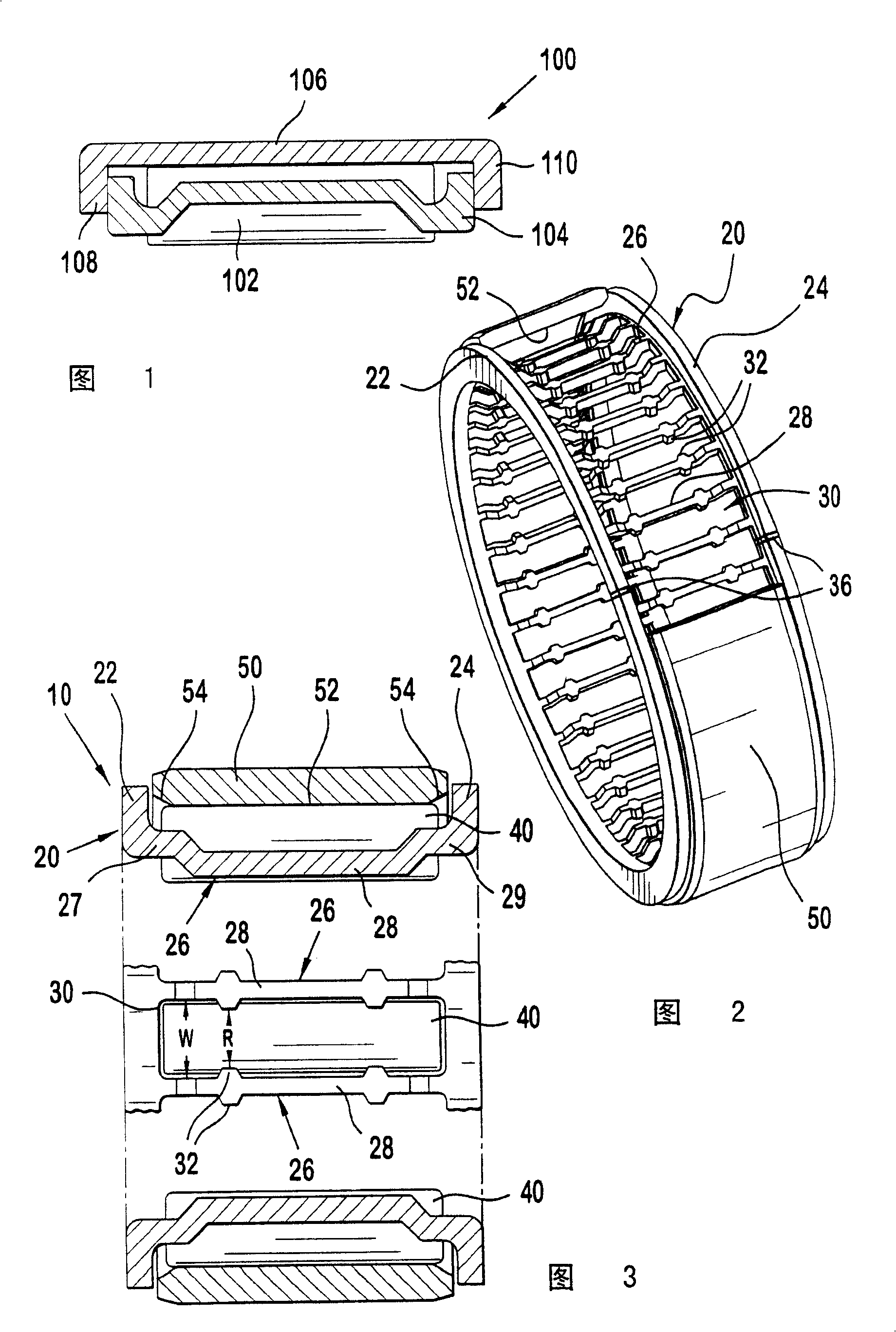
[0012] Referring to Figures 2 and 3, a bearing assembly 10 according to a first specific embodiment of the present invention is described. The bearing assembly 10 generally includes a bearing cartridge 20 , a plurality of rollers 40 and a sleeve 50 . The bearing cartridge 20 of this embodiment has radial flanges 22 and 24 connected together by a cross arm 26 . Cross arm 26 has a central portion 28 that is offset radially inwardly from laterally outward portions 27 and 29 . Bearing cartridge 20 may be manufactured from a stamped sheet rolled to form a hoop which is then welded, for example at 36 in FIG. 2 . Of course other manufacturing methods can also be used.

[0013] Adjacent spaced apart cross arms 26 define a plurality of roller retention slots or pockets 30 surrounding the bearing cartridge 20 . Each retaining slot or pocket 30 is sized to retain a roller 40 for rotation therein. In this embodiment, the radially inward central portion 28 includes a plurality of circu...


PUM


Abstract

A bearing assembly comprising a cage, a plurality of rollers and a sleeve. The cage comprises a central portion extending between a pair of radial flanges. The central portion includes a plurality of roller retaining pockets configured to receive and prevent substantial radial movement of rollers positioned therein in a radial direction. The sleeve is positioned between the radial flanges with the radial flanges radially overlapping the sleeve. The sleeve is retained between the flanges prevents substantial radial movement of the rollers in the opposite direction.

Description

technical field [0001] The present invention generally relates to a roller bearing, and more particularly to a composite roller bearing assembly. Background technique [0002] FIG. 1 illustrates a prior art roller bearing assembly 100 . The roller bearing assembly 100 generally includes a plurality of rollers 102 retained within a bearing housing 104 . Bearing cartridge 104 includes a plurality of pockets for positioning and retaining rollers 102 . A cover 106 is disposed on the outside of the bearing housing 104 and roller 102 assembly to provide an outer bearing surface for the roller 102 . Optionally, a cover 106 may be disposed on the inside of the bearing housing 104 and roller 102 assembly to provide an inner bearing surface for the roller 102 . Flanges 108 and 110 extend radially from cover 106 to combine the bearing assembly, thereby enabling cover 106 to resist radially outward movement of rollers 102 . Various methods can be used to construct the cassette, for ...

Claims


Application Information

Patent Timeline
IPC IPC(8): F16C33/46F16C33/54F16C19/26
CPCF16C33/543F16C19/44F16C19/466
Inventor M·T·塔科夫斯基
Owner KOYO BEARINGS NORTH AMERICA LLC
Features
  • R&D
  • Intellectual Property
  • Life Sciences
  • Materials
  • Tech Scout
  • Unparalleled Data Quality
  • Higher Quality Content
  • 60% Fewer Hallucinations
Learn More