Light conductive board and its producing method

A technology for light guide plates and plates, applied in the directions of light guides, optics, optical components, etc., can solve the problems of insufficient diversification and miniaturization of microstructures, unfavorable thinning of display devices, complex structures of backlight modules, etc., and achieve the realization of grooves. Diversified, uniform and bright outgoing light, simplifying the effect of the backlight module

Inactive Publication Date: 2008-12-24
SHENZHEN JINGJIANG YUNCHUANG TECH CO LTD
View PDF8 Cites 0 Cited by
  • Summary
  • Abstract
  • Description
  • Claims
  • Application Information

AI Technical Summary

Problems solved by technology

[0013] In order to solve the complex structure of the backlight module in the prior art non-self-luminous flat-panel display device, which is not conducive to the thinning of the display device, the microstructure formed on the light guide plate in the backlight module by the traditional method is not diverse and fine, and the manufacturing process is complicated. , high cost technical problem, the first purpose of the present invention is to provide a light guide plate that ensures brightness and uniformity and simplifies the backlight module

Method used


Image

  • Light conductive board and its producing method
  • Light conductive board and its producing method
  • Light conductive board and its producing method

Examples


Embodiment Construction

[0028] The light guide plate provided by the present invention and its preparation method are described below in conjunction with the accompanying drawings:

[0029] like Figure 11 As shown, the preparation method of the light guide plate provided by the present invention comprises the following steps:

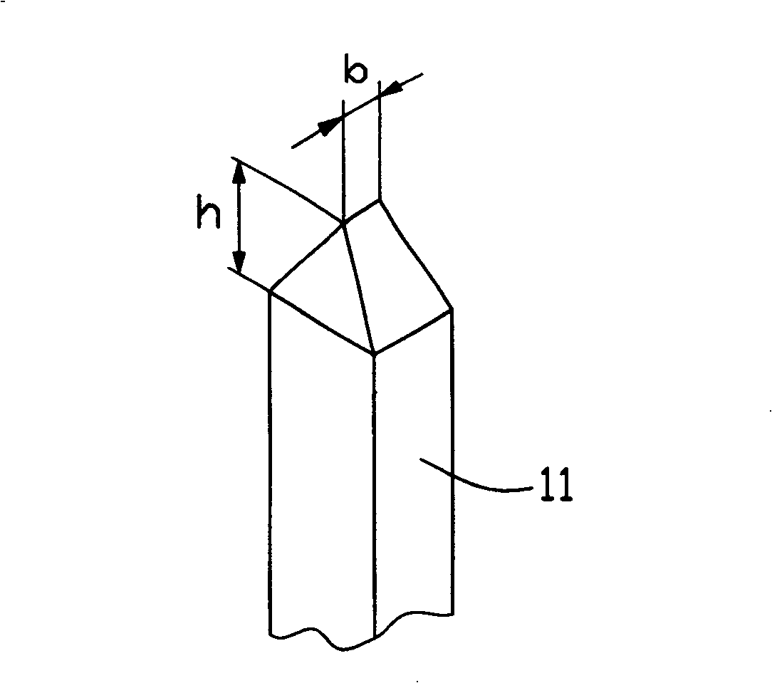
[0030] Step 10, provide an embossing machine with a plurality of indenters of different shapes; the indenters are generally made of diamond and other hard and wear-resistant materials through fine processing, and have a long service life.

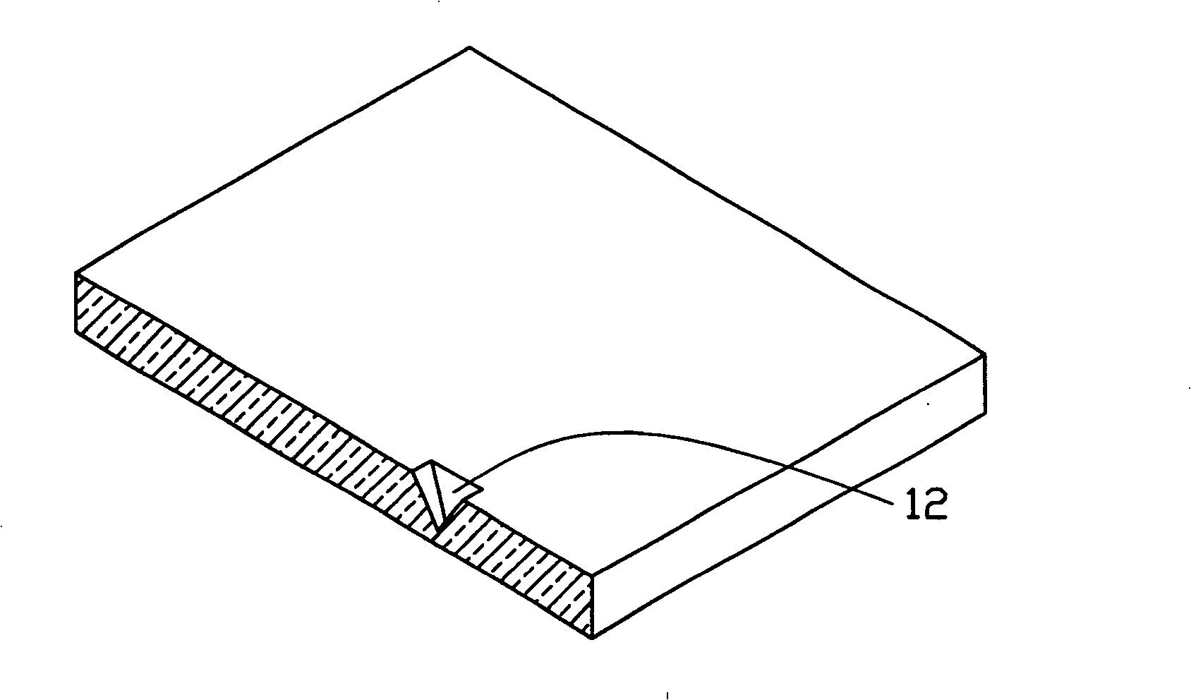
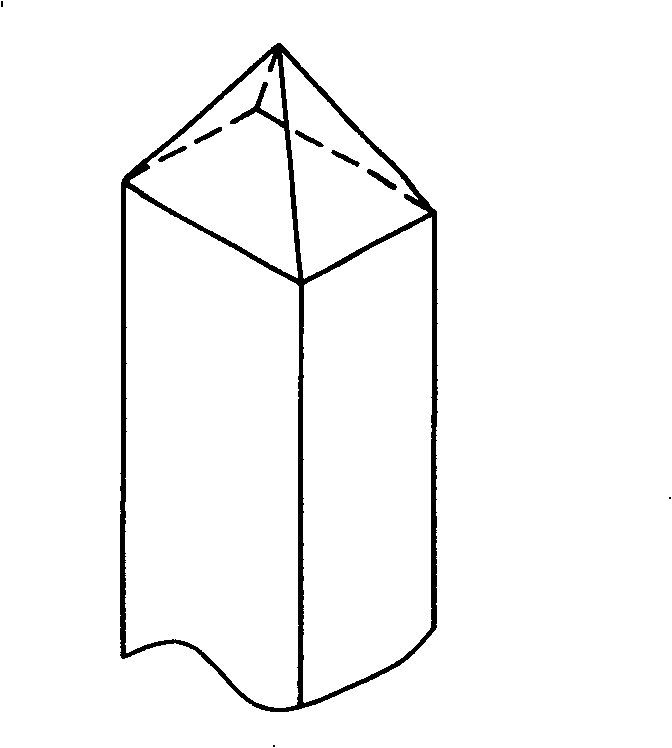
[0031] The indenter has such figure 1 , image 3 , Figure 4 , Figure 5 The different pyramid or conical shapes shown may also have other shapes such as spherical or prismatic, which can be freely designed according to optical design requirements, and are not limited to cone, spherical or cylindrical. The conical indenter can imprint a groove with a V-shaped axial section, the cylindrical indenter can imprint a groove with a U-shape...


PUM


Abstract

The invention relates to a light guide plate and a preparation method thereof. The light guide plate includes a light-incident surface, a light-emitting surface and a reflecting surface opposite to the light-emitting surface. A plurality of grooves with arc-shaped axial cross-sections and an axial cross-section are formed on at least one of the three surfaces. Angular grooves, the two grooves are arranged according to predetermined optical pattern rules. The groove with an arc-shaped axial section can adjust the uniformity of the beam surface; the groove with an angular axial section can adjust the directionality of the beam, so that the beam can be emitted from the light-emitting surface of the light guide plate within a certain distribution angle, enhancing the range of the beam. Beam brightness. Therefore, the light guide plate provided by the present invention can make the light emitted from its light exit surface uniform and bright, and is suitable for use in the backlight module of a non-self-luminous flat display. The invention also provides a method for preparing the light guide plate.

Description

【Technical field】 [0001] The invention relates to a light guide plate and a preparation method thereof, in particular to a light guide plate used for a backlight module of a non-self-illuminating flat panel display and a preparation method thereof. 【Background technique】 [0002] The light source of the non-self-illuminating flat-panel display (such as liquid crystal display) comes from the flat light source module, the transmissive liquid crystal display uses the backlight module, and the reflective display uses the front light module. The backlight module is a module structure that converts linear light sources (such as cold cathode tubes) or point light sources (such as light-emitting diodes) into planar light sources with high brightness and surface uniformity. [0003] like Figure 12 and Figure 13 As shown, it is the structure of a traditional backlight module: the cold cathode tube 1 is placed on the end surface of the light guide plate 2, the reflective surface of ...

Claims


Application Information

Patent Timeline
Patent Type & Authority Patents(China)
IPC IPC(8): G02F1/1335B30B1/00
CPCG02B6/0036G02B6/0061G02B6/0065
Inventor 中川威雄中村文夫后藤典雄李军旗
Owner SHENZHEN JINGJIANG YUNCHUANG TECH CO LTD
Why Eureka
Try Eureka