Air transport device for fuel cell engine at atmospheric operation
An air conveying device and fuel cell technology, which is applied in the direction of fuel cells, fuel cell additives, electrical components, etc., can solve the problems that there is no way to meet the flat installation requirements of fuel cell engines, and the diameter of fan drums is large.
- Summary
- Abstract
- Description
- Claims
- Application Information
AI Technical Summary
Problems solved by technology
Method used
Image

Examples
Embodiment 1
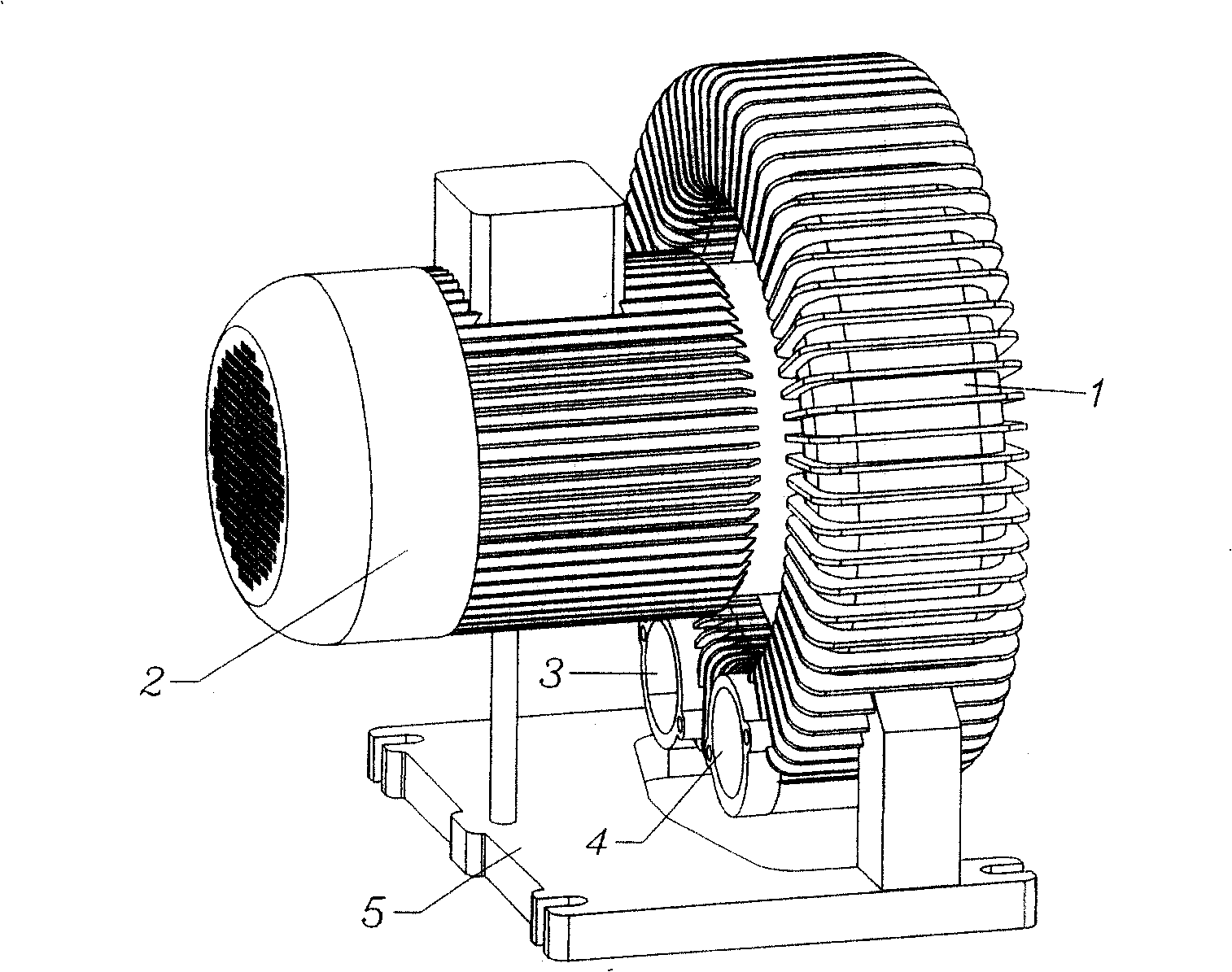
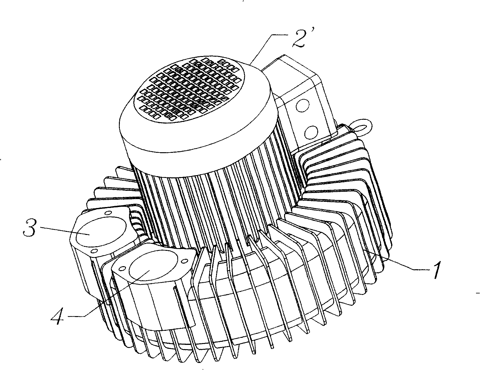
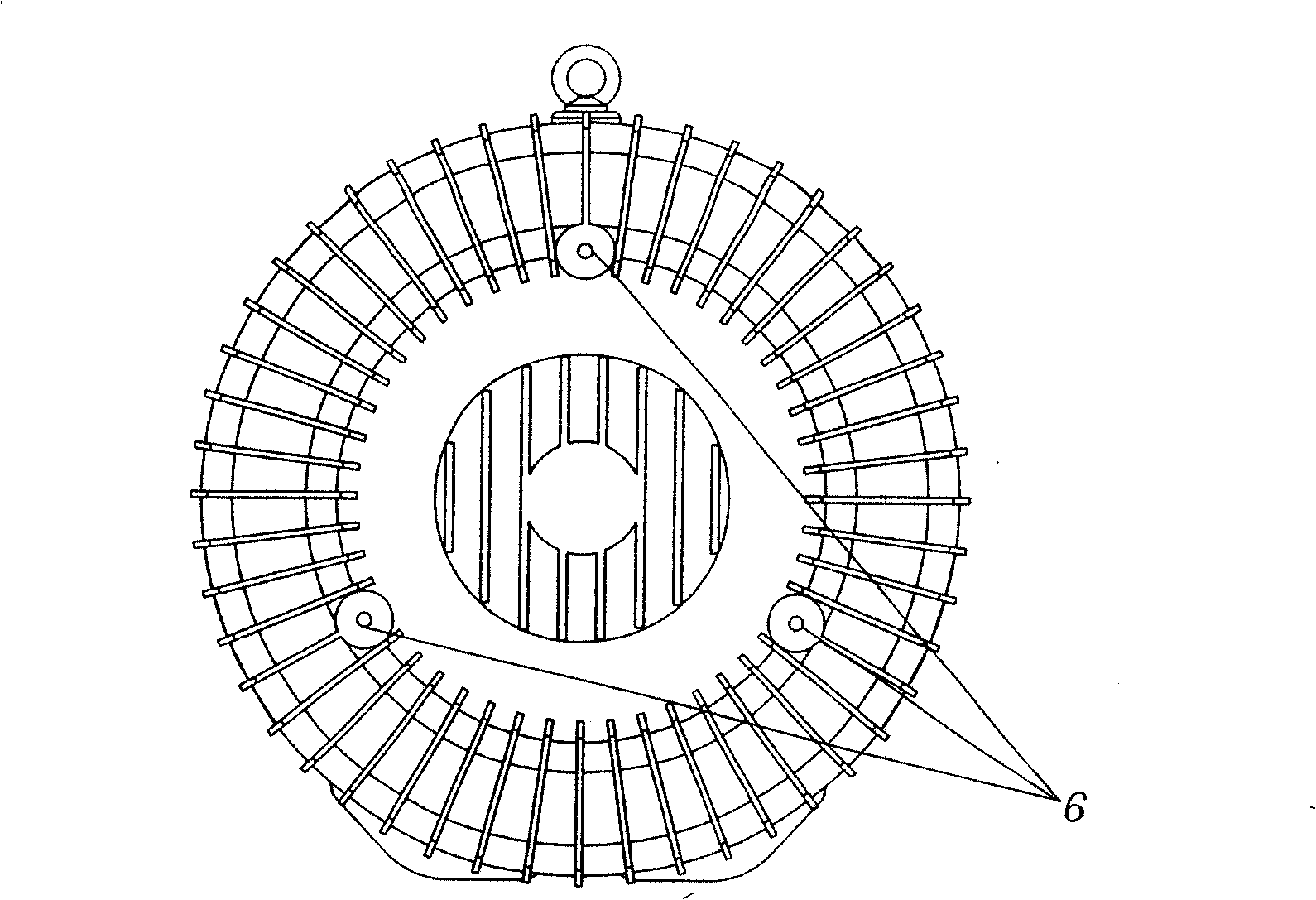
[0036] Such as figure 2 , image 3 Shown, a kind of 50 kilowatts normal pressure operation fuel cell engine air conveying device, comprises flat motor 2 ' (diameter φ 170mm), wind drum 1 (diameter φ 360mm), and described motor 2 ' is located at a part of wind drum 1 The side end face, and the rotation axis of the motor 2' is perpendicular to the air drum 1, the flattened height of the whole air conveying device is 280mm, the air drum 1 is provided with an air suction port 3 and an air outlet 4, and the air suction port 3, the air outlet The tuyere 4 is arranged on the motor side end face of the air drum 1, and the air suction port 3 and the air outlet 4 are arranged axially with the air drum 1; it also includes three evenly arranged installation holes 6, which are arranged on the air drum 1 The other end face of the wind drum 1 is installed axially with the wind drum 1; the wind drum 1 is directly installed as a mounting base, and the end face of the wind drum 1 is parallel ...
Embodiment 2
[0038] Such as Figure 4As shown, a 50 kilowatt fuel cell engine air conveying device operated at normal pressure includes a flat motor 2' (diameter φ170mm), wind drum 1 (diameter φ360mm), and the motor 2' is located on one side of the wind drum 1 The side end face, and the rotation axis of the motor 2' is perpendicular to the air drum 1, the flattened height of the whole air conveying device is 280mm, the air drum 1 is provided with an air suction port 3 and an air outlet 4, and the air suction port 3, the air outlet The tuyere 4 is arranged on the motor side end face of the air drum 1, and the air suction port 3 and the air outlet 4 are arranged axially with the air drum 1; it also includes five evenly arranged installation holes, which are arranged at the tail of the motor 2' end, and is arranged axially with the motor 2'; the motor 2' is directly installed as an installation base, and the rotation axis of the motor is perpendicular to the ground.
Embodiment 3
[0040] Such as Figure 5 Shown, a kind of fuel cell engine air conveying device of 50 kilowatts normal pressure operation, the air suction port 3 of this device, the air outlet 4 are arranged on the circumferential surface of the air drum 1, and the air suction port 3, the air outlet 4 are connected with the air drum 1 is arranged radially; other structures are the same as in Embodiment 1.
PUM
 Abstract
Description
Claims
Application Information
 - R&D
- Intellectual Property
- Life Sciences
- Materials
- Tech Scout
- Unparalleled Data Quality
- Higher Quality Content
- 60% Fewer Hallucinations
Browse by: Latest US Patents, China's latest patents, Technical Efficacy Thesaurus, Application Domain, Technology Topic, Popular Technical Reports.
© 2025 PatSnap. All rights reserved.Legal|Privacy policy|Modern Slavery Act Transparency Statement|Sitemap|About US| Contact US: help@patsnap.com