
Appartus for transporting metal working piece

A technology for transporting devices and metal workpieces, applied in furnace components, manufacturing tools, lighting and heating equipment, etc., can solve problems such as prolonged movement implementation time, movement interruption, etc., to achieve reliable force transmission and low cost.

Inactive Publication Date: 2009-08-12
IPSEN INT INC
View PDF7 Cites 0 Cited by
  • Summary
  • Abstract
  • Description
  • Claims
  • Application Information

AI Technical Summary

Problems solved by technology

[0004] Due to these positional deviations, problems have arisen in the past when connecting the transport means, which in a disadvantageous manner results in prolonged implementation of the movement or even an interruption of the movement

Method used


Image

  • Appartus for transporting metal working piece
  • Appartus for transporting metal working piece
  • Appartus for transporting metal working piece

Examples


Embodiment Construction

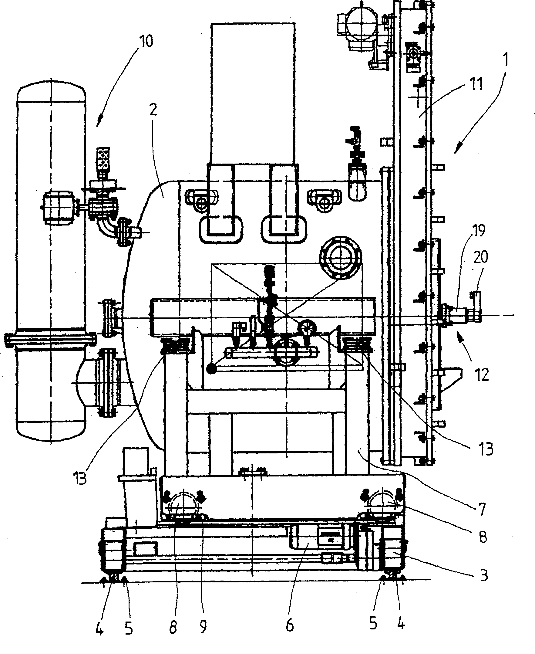
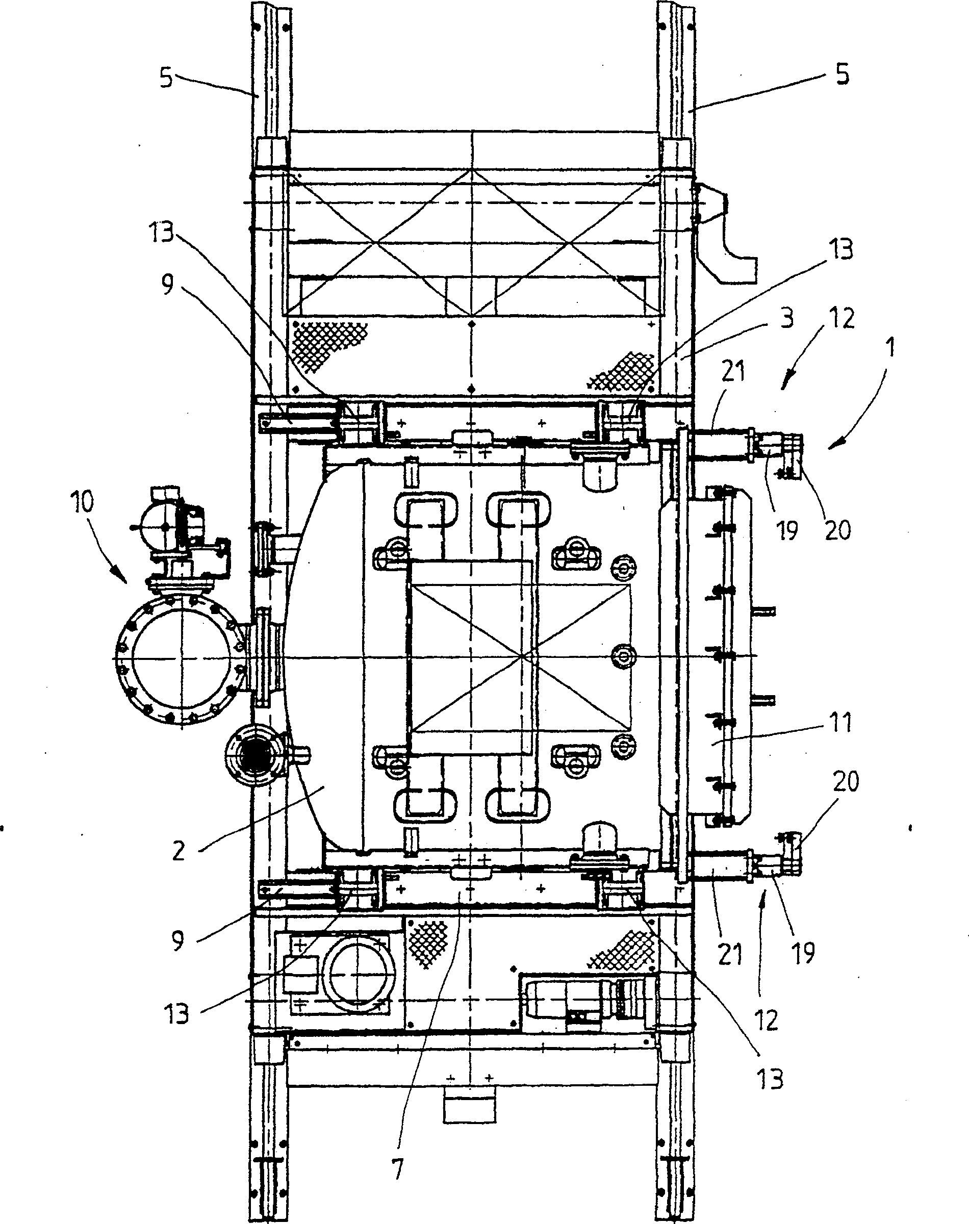
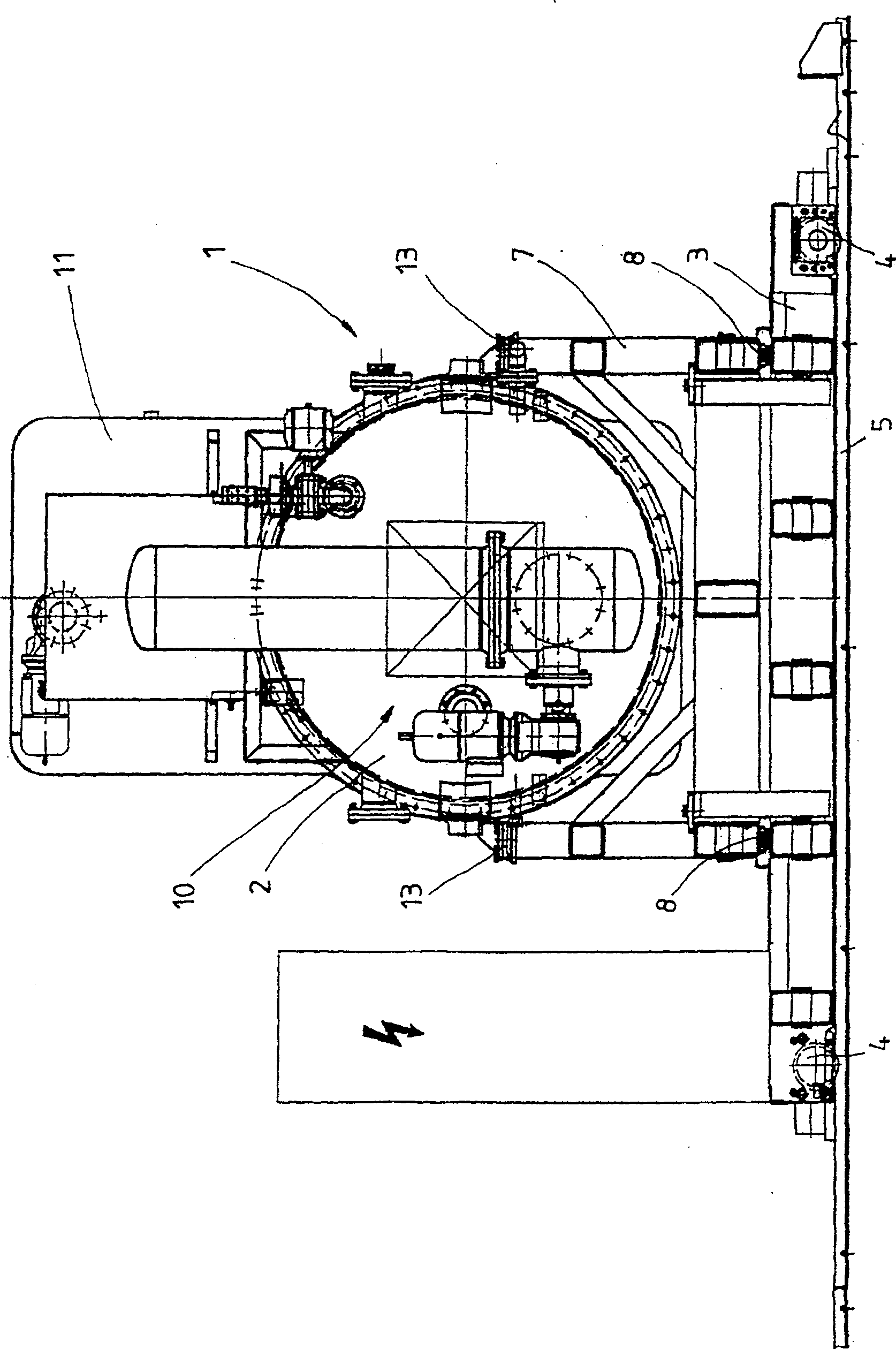
[0027] Figure 1-3 A device for transporting metal workpieces is shown, wherein the device 1 shown here has a transport device in the form of an externally insulated and vacuum-tight cylindrical transport chamber 2 . The transport chamber 2 is used for receiving and transporting workpieces, not shown in detail in the figure, which are arranged together in one batch.

[0028] Furthermore, the device 1 comprises a running gear 3, with which the transport chamber 2 can be moved horizontally. The chassis 3 preferably consists of a frame structure (not shown in detail) and is moved by means of corresponding wheels 4 on rails 5 formed for this purpose. The motor 6 arranged on the running gear 3 is used for driving. The transport device, which is formed as the transport chamber 2 , is supported by a frame 7 which is for its part movably arranged on this mechanism perpendicular to the direction of movement of the running gear 3 . For this purpose, the frame 7 has wheels 8 , by mean...


PUM


Abstract

The device (1) is for transporting metallic workpieces, particularly during heat treatment and comprises a transport unit (2) which is moved horizontally by a movement mechanism (3). The transport unit is borne by a frame (7) relatively movable to the movement mechanism. The transport unit is floatingly located in relation to the frame, by means of elastic bearing bodies (13), preferably made of rubber. The elastic bearing bodies have at least one preferably steel inlay plate. The transport unit (2) is a heat-insulated and gas and / or vacuum-tight transport chamber. For a vacuum-tight connection, the transport unit has a connection side tension device (12). The tension device is formed by at least two tension units movable relatively to the transport chamber, which engage in the tension position in abutments formed on a counter module.

Description

technical field [0001] The invention relates to a device for transporting metal workpieces, in particular during heat treatment, with a transport device and a running gear for horizontally moving the transport device. Background technique [0002] Devices of the above-mentioned type are disclosed in the prior art, for example EP 1 229 137, and are proven in daily practical use. Their function is to transport workpieces that are to be transported to different heat treatment chambers within the framework of the heat treatment in a simple manner and, as required, to the respective heat treatment chamber. It is particularly advantageous in this respect that the transport device can be moved independently of the respective modular heat treatment chamber, so that the user can use the individual treatment chambers in a different sequence if desired. In order to ensure that the workpieces to be processed are only exposed to a predetermined atmosphere during transport, according to ...

Claims


Application Information

Patent Timeline
Patent Type & Authority Patents(China)
IPC IPC(8): C21D9/00F27D3/00F27D3/12
CPCC21D9/0018F27D3/12
Inventor 莫伊尔斯·海因茨黑塞·托尔斯滕
Owner IPSEN INT INC
Learn More