Distributing capacitance current and transition resistance influence resisting line one-end fault ranging method

A transition resistance and distributed capacitance technology, applied in the field of power systems, can solve problems such as difficult decoupling, unacceptable errors, and poor anti-transition resistance

Active Publication Date: 2009-08-12
TSINGHUA UNIV
View PDF6 Cites 0 Cited by
  • Summary
  • Abstract
  • Description
  • Claims
  • Application Information

AI Technical Summary

Problems solved by technology

The hyperbolic tangent function characteristic determines that its ability to resist transition resistance is very poor, and the additional measurement impedance brought by transition resistance will seriously affect the accuracy of fault location
The improvement scheme of the traditional impedance method: if the reactance component is used for fault location, and the influence of the transition resistance is partially eliminated, it is no longer applicable to the fault location method modeled by the distributed parameter line model, mainly because the line impedance Z mea It is a nonlinear function of line resistance, inductance, and capacitance per unit length, and it is difficult to decouple; other solutions such as assuming that the impedance of the opposite end system is known or assuming that the current at the fault point is in the same phase as the current at the observation point, the super / On UHV long lines, the error caused is unacceptable, so it is difficult to directly apply the traditional single-ended impedance fault location method to EHV / UHV long lines

Method used


Image

  • Distributing capacitance current and transition resistance influence resisting line one-end fault ranging method
  • Distributing capacitance current and transition resistance influence resisting line one-end fault ranging method
  • Distributing capacitance current and transition resistance influence resisting line one-end fault ranging method

Examples


Embodiment Construction

[0037] The embodiment of the line single-ended fault location method against the influence of distributed capacitive current and transition resistance proposed by the present invention is described in detail as follows:

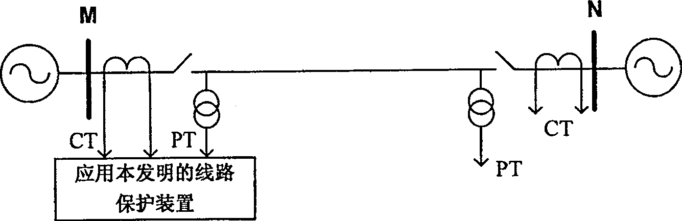
[0038] A type of 1000kV UHV power transmission system applying the present invention is as follows figure 1 As shown, the system is a typical double-ended power supply system, the busbars on both sides are M and N respectively, the line length is 800km, and the line parameter values ​​are shown in Table 1. The system impedance parameters on both sides are as follows. The angle of the N-side power source is 44 degrees behind the M-side, and the potentials of the M-side and N-side are 1.1062 and 1.1069 times the rated voltage respectively. The fault distance measuring device applying the method of the present invention is installed on the M side, and the voltage and current come from the line side voltage transformer (PT) and current transformer (CT) respectively...


PUM


Abstract

The invention belongs to the field of electric power systems, and in particular relates to a line single-end fault ranging method against the influence of distributed capacitive current and transition resistance. Including: measuring the fault phase voltage, phase current, zero-sequence voltage, zero-sequence current and negative-sequence current at the protection installation of the substation as input quantities; using the time when the voltage at the fault point crosses zero, the measured impedance is not affected by the transition resistance. Starting from the beginning of the protection line, calculate the calculated value of the real part of the measured voltage at the moment when the voltage at the fault point crosses zero, compare it with the measured value of the real part of the measured voltage, and calculate the error value; and use ΔS as the step size to calculate in turn the setting of the protection that sends the trip signal range, if the protection trip signal cannot be obtained, then search the entire length of the protected line, and take the point with the smallest error as the fault point; the method of the present invention is not affected by the distributed capacitive current, is not affected by the transition resistance, and does not have the method of solving the equation The pseudo-root problem and non-convergence problem of iterative method have high practical value.

Description

technical field [0001] The invention belongs to the field of power systems, and in particular relates to a line single-end fault distance measurement method that is resistant to the influence of distributed capacitive current and transition resistance. Background technique [0002] The transmission line is responsible for the important task of transmitting electric energy, and its failure directly threatens the safe operation of the power system. In particular, China's voltage level is developing from ultra-high voltage (represented by 500kV) to ultra-high voltage (represented by 1000kV), and the capacity of transmission lines is further increased. The stability of the power system and ensuring the safe and stable operation of the system are of great significance. [0003] Fault location methods are divided into two types from the perspective of using electrical quantities: single-ended method and double-ended method. The double-ended method requires the use of electrical ...

Claims


Application Information

Patent Timeline
Patent Type & Authority Patents(China)
IPC IPC(8): G01R31/08
Inventor 董新洲王宾
Owner TSINGHUA UNIV
Why Eureka
Try Eureka