Impact test apparatus and impact test method
A technology of impact test and impact force, which is applied in the direction of measuring device, testing the strength of materials and instruments using one impact force
- Summary
- Abstract
- Description
- Claims
- Application Information
AI Technical Summary
Problems solved by technology
Method used
Image
Examples
Embodiment 1
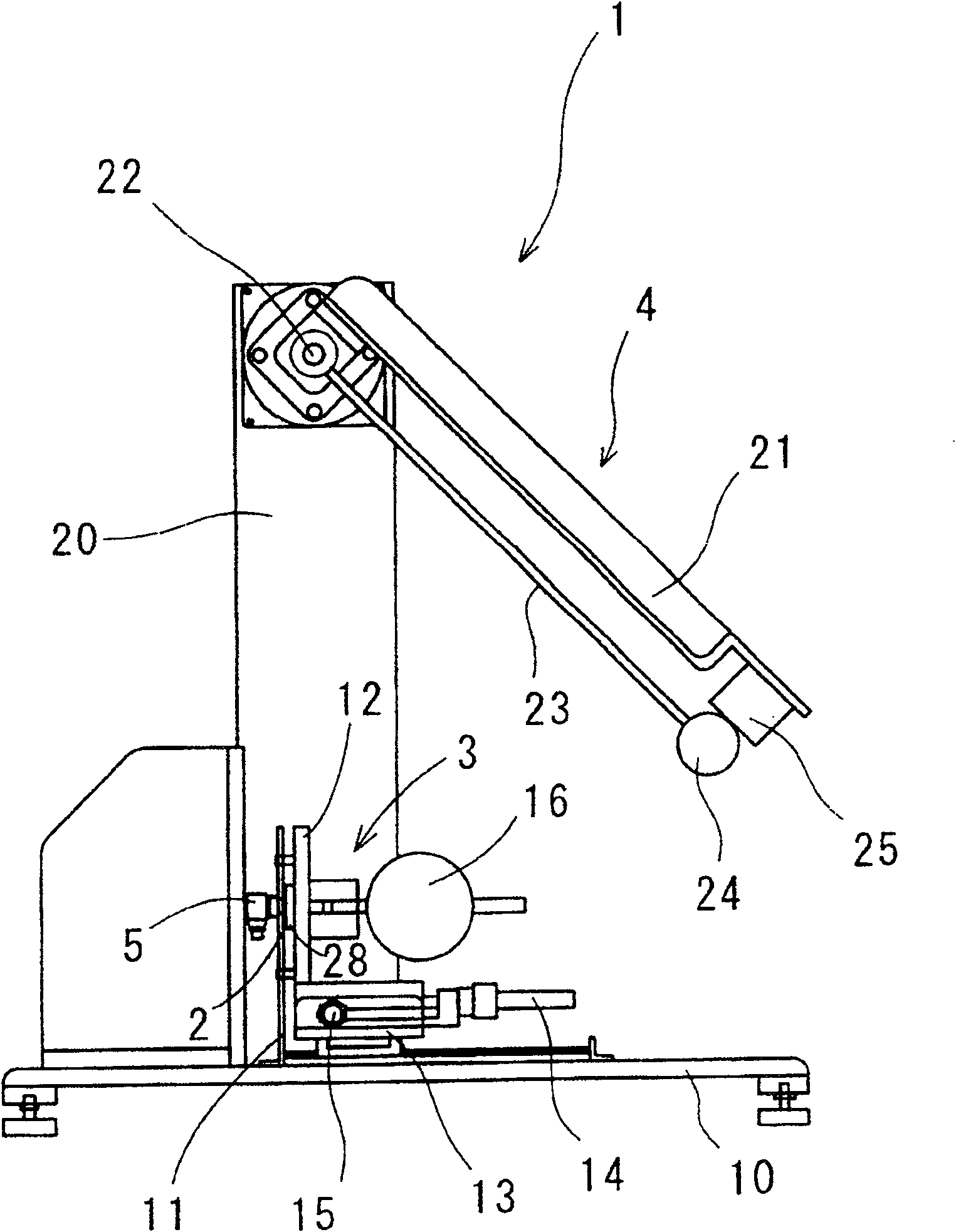
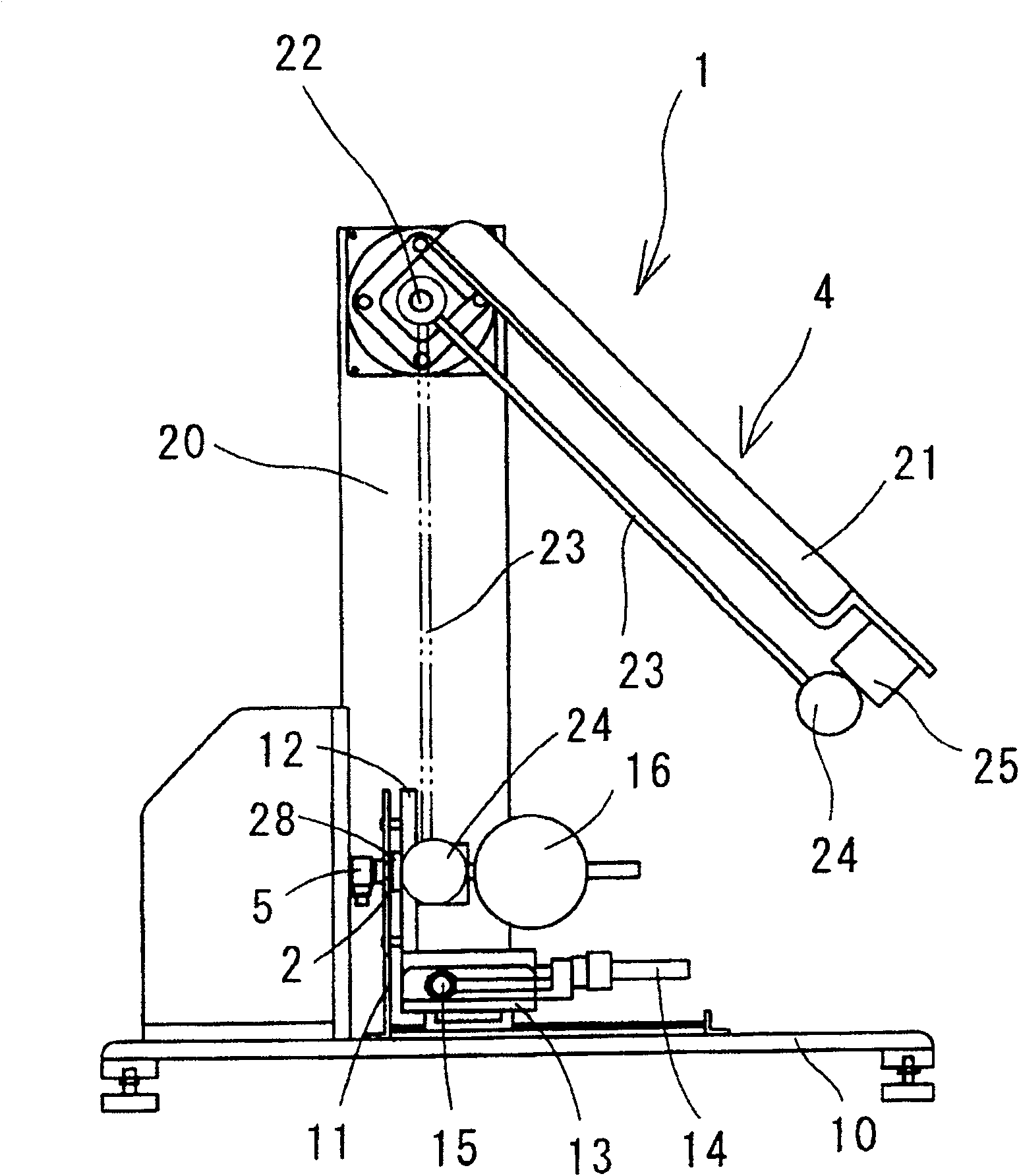
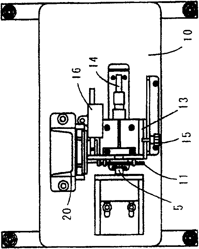
[0027] First, refer to Figure 1 to Figure 4 A schematic configuration of the impact test apparatus of the first embodiment will be described.
[0028] Such as Figure 1 to Figure 4 As shown, the impact test device 1 in the first embodiment is composed of the following components: a holding device 3, which is used to hold a test piece 2 with any active force; an impact application device 4, which is used to The test piece 2 applies an impact stress; a force sensor 5, as an impact force sensing device, is used to sense the impact force acting on the test piece 2 by the impact application device 4; a high-speed camera 6, as a displacement A detection device for detecting displacement of the test piece when the impact applying device 4 applies impact force to the test piece 2; and an output device 7 for synchronizing the signal from the force sensor 5 with the signal from the high-speed camera 6 , and output an impact stress-strain characteristic curve, which is used as the imp...
Embodiment 2
[0054] Below, will refer to Figure 7 to Figure 9 The schematic configuration of the impact test apparatus of the second embodiment will be described. Here, in the following description, as in Figure 1 to Figure 4 The same reference numerals in the shown configuration and the like of the impact test apparatus 1 of the first embodiment designate the same or equivalent components as the configuration and the like of the impact test apparatus 1 of the first embodiment.
[0055] The schematic configuration and control structure of the impact test device in the second embodiment are almost identical to the corresponding structure of the impact test device 1 in the first embodiment.
[0056] However, if Figure 7 to Figure 9 As shown, the impact test device 51 of the second embodiment is different from the structure of the impact test device 1 of the first embodiment, because the holding device 3 and the impact applying device 4 on which the force sensor 5 is fixed are arranged i...
Embodiment 3
[0086] Such as Figure 11 As shown, for example, an acceleration sensor 81 is fixed at a position close to the collision between the hammer 24 and the support plate 28 to replace the design of using the above-mentioned high-speed camera 6 to measure the displacement of the test piece 2, and when the hammer 24 collides with the support plate 28 On collision, the acceleration is integrated twice. With such a design, the displacement of the specimen 2 can also be obtained.
PUM
 Abstract
Description
Claims
Application Information
 - R&D
- Intellectual Property
- Life Sciences
- Materials
- Tech Scout
- Unparalleled Data Quality
- Higher Quality Content
- 60% Fewer Hallucinations
Browse by: Latest US Patents, China's latest patents, Technical Efficacy Thesaurus, Application Domain, Technology Topic, Popular Technical Reports.
© 2025 PatSnap. All rights reserved.Legal|Privacy policy|Modern Slavery Act Transparency Statement|Sitemap|About US| Contact US: help@patsnap.com


