Impact test apparatus and impact test method

A technology of impact test and impact force, applied in the direction of measuring device, testing material strength using one impact force, instrument, etc.

Inactive Publication Date: 2006-01-11
NITTO DENKO CORP
View PDF0 Cites 24 Cited by
  • Summary
  • Abstract
  • Description
  • Claims
  • Application Information

AI Technical Summary

Problems solved by technology

Therefore, based on the same principle, it is difficult to evaluate these impact-absorbing materials using traditional impact test methods or repulsion elasticity test methods

Method used


Image

  • Impact test apparatus and impact test method
  • Impact test apparatus and impact test method
  • Impact test apparatus and impact test method

Examples


Embodiment 1

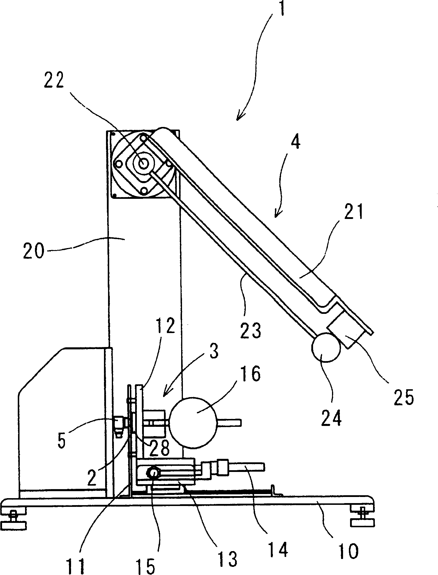
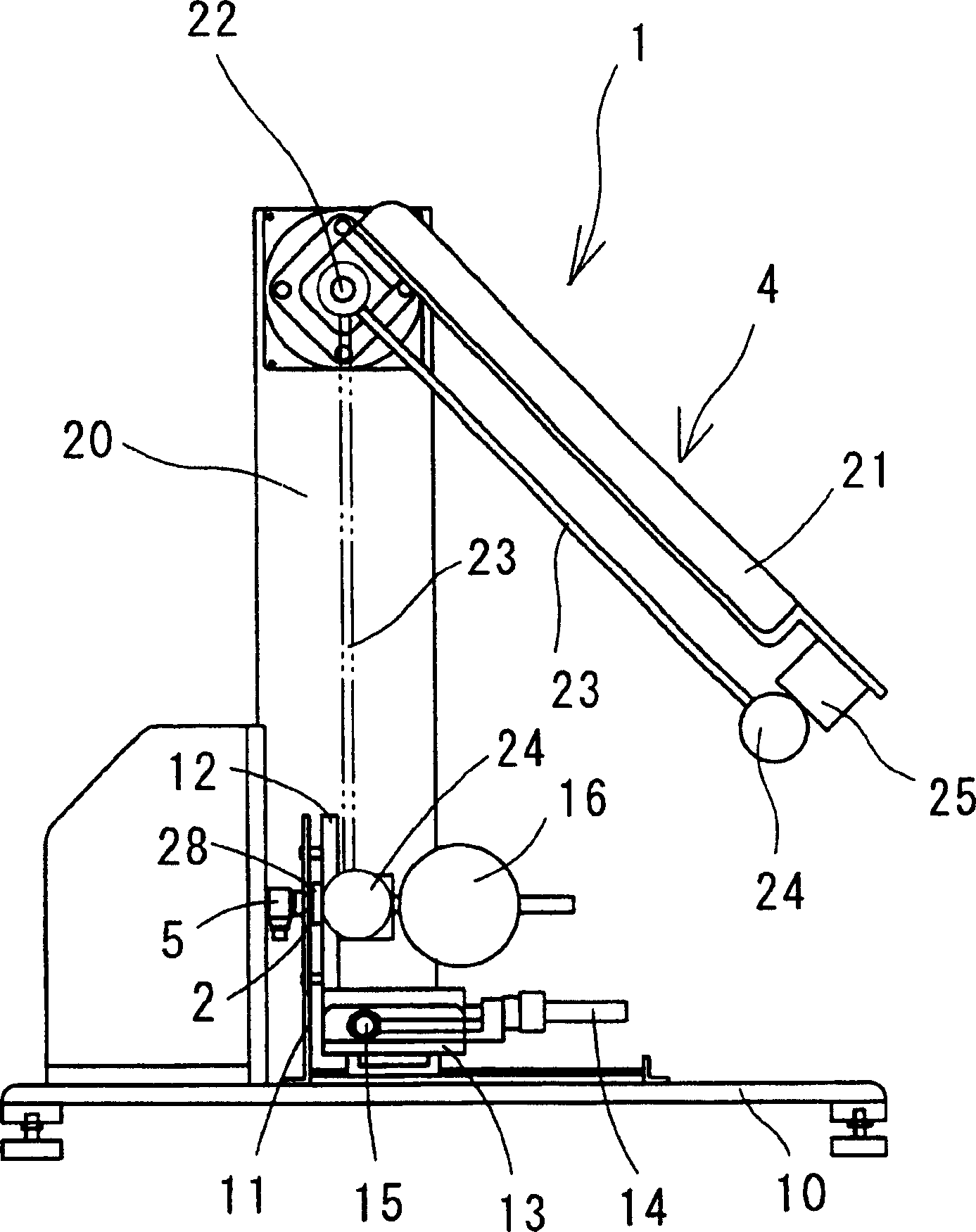
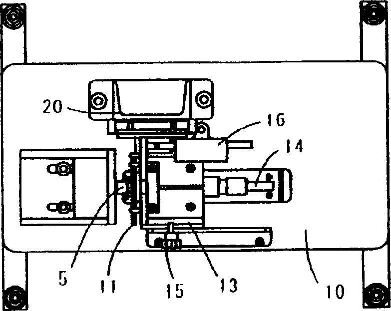
[0027] First, refer to Figure 1 to Figure 4 A schematic configuration of the impact test apparatus of the first embodiment will be described.

[0028] Such as Figure 1 to Figure 4 As shown, the impact test device 1 in the first embodiment is composed of the following components: a holding device 3, which is used to hold a test piece 2 with any active force; an impact application device 4, which is used to The test piece 2 applies an impact stress; a force sensor 5, as an impact force sensing device, is used to sense the impact force acting on the test piece 2 by the impact application device 4; a high-speed camera 6, as a displacement A detection device for detecting displacement of the test piece when the impact applying device 4 applies impact force to the test piece 2; and an output device 7 for synchronizing the signal from the force sensor 5 with the signal from the high-speed camera 6 , and output an impact stress-strain characteristic curve, which is used as the imp...

Embodiment 2

[0054] Below, will refer to Figure 7 to Figure 9 The schematic configuration of the impact test apparatus of the second embodiment will be described. Here, in the following description, as in Figure 1 to Figure 4 The same reference numerals in the shown configuration and the like of the first embodiment impact test apparatus 1 designate the same or equivalent components as the configuration and the like of the first embodiment impact test apparatus 1 .

[0055]The schematic configuration and control structure of the impact test device in the second embodiment are almost identical to the corresponding structure of the impact test device 1 in the first embodiment.

[0056] However, if Figure 7 to Figure 9 As shown, the impact test device 51 of the second embodiment is different from the structure of the impact test device 1 of the first embodiment, because the holding device 3 and the impact applying device 4 on which the force sensor 5 is fixed are arranged in a constant t...

Embodiment 3

[0086] Such as Figure 11 As shown, for example, an acceleration sensor 81 is fixed at a position close to the collision between the hammer 24 and the support plate 28 to replace the design of using the above-mentioned high-speed camera 6 to measure the displacement of the test piece 2, and when the hammer 24 collides with the support plate 28 On collision, the acceleration is integrated twice. With such a design, the displacement of the specimen 2 can also be obtained.


PUM


Abstract

The present invention provides an impact test apparatus including a holding device for holding a test piece at an arbitrary holding force, an impact applying device for applying an impact force to the test piece held by the holding device, a force sensor for sensing the impact force applied to the test piece by the impact applying device, a high-speed camera for detecting a displacement of the test piece when applied with the impact force by the impact applying device, and an output device for synchronizing a signal from the force sensor with a signal from the high-speed camera and outputting an impact stress-strain characteristic curve when the impact force is applied to the test piece.

Description

technical field [0001] The invention relates to an impact test device and an impact test method, which can measure the impact stress-strain characteristics of a test piece. Background technique [0002] Conventionally, the Izod impact test or the Charpy impact test has been considered as a method for measuring the impact strength of materials (for example, see Japanese Patent Application Publication No. H2 [1990]-13825). According to these test methods, when an impact energy (impact force) is applied to a test piece to break the test piece, the impact strength of the test piece can be measured based on the impact energy. However, in the case where the test piece is made of a shock-absorbing material made of foam material, viscoelastic material, or a combination of these two materials. Therefore, it is difficult to determine the impact force applied to the test piece, and the impact stress-strain characteristics of the test piece when the impact force is applied to the test...

Claims


Application Information

Patent Timeline
Patent Type & Authority Applications(China)
IPC IPC(8): G01N3/30G01N3/02
Inventor 畑中武藏杉原保则吉田纯二安积由起子阴久裕毅
Owner NITTO DENKO CORP
Why Eureka
Try Eureka