Eureka AIR delivers breakthrough ideas for toughest innovation challenges, trusted by R&D personnel around the world.

Electricity-free holding contactor

A technology of maintaining contact and contactor, applied in the direction of non-polar relays, etc., can solve the problem of restricting the use of non-electrical maintaining contactor, etc., and achieve the effect of simple structure, easy implementation and effective disconnection.

Inactive Publication Date: 2010-02-03
韩天鹏
View PDF4 Cites 0 Cited by
  • Summary
  • Abstract
  • Description
  • Claims
  • Application Information

AI Technical Summary

Problems solved by technology

However, at present, there is no suitable structure that can make the moving iron core and static iron core in the state of no electricity hold to overcome the resistance of the holding mechanism to re-disconnect, thus limiting the use of the no electricity hold contactor

Method used


Image

  • Electricity-free holding contactor
  • Electricity-free holding contactor
  • Electricity-free holding contactor

Examples


Embodiment Construction

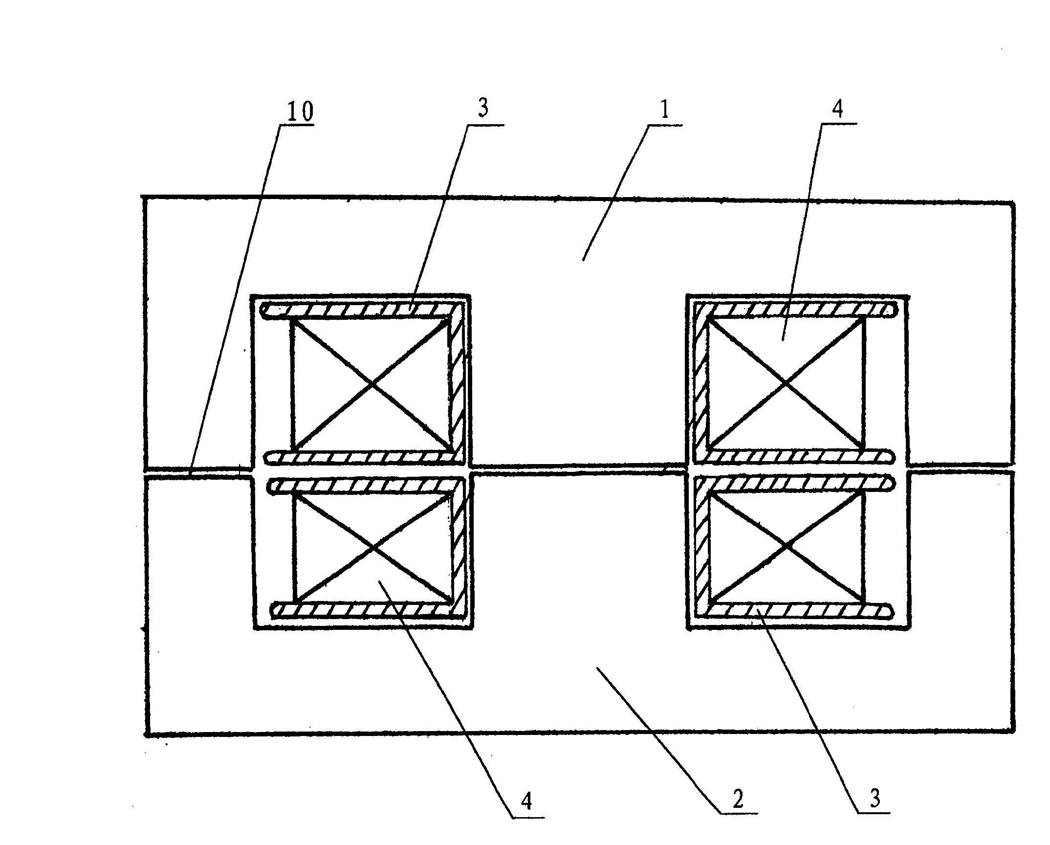
[0014] Such as figure 1 As shown, the iron absorber of the non-electric holding contactor is composed of a moving iron core 1 and a static iron core 2. The coil support 3 arranged around the core column of the iron absorber is two sections separated from each other, and the two coil supports are respectively located on the moving iron core. The core and the core column periphery of the static iron core, the electromagnetic coil 4 is also divided into two groups, which are respectively wound on two sections of coil supports. In this way, when the current in the same direction is passed through the two sets of coils, the moving iron core and the static iron core are attracted; and when the reverse current is passed through the two sets of coils, the moving iron core and the static iron core can be repelled.

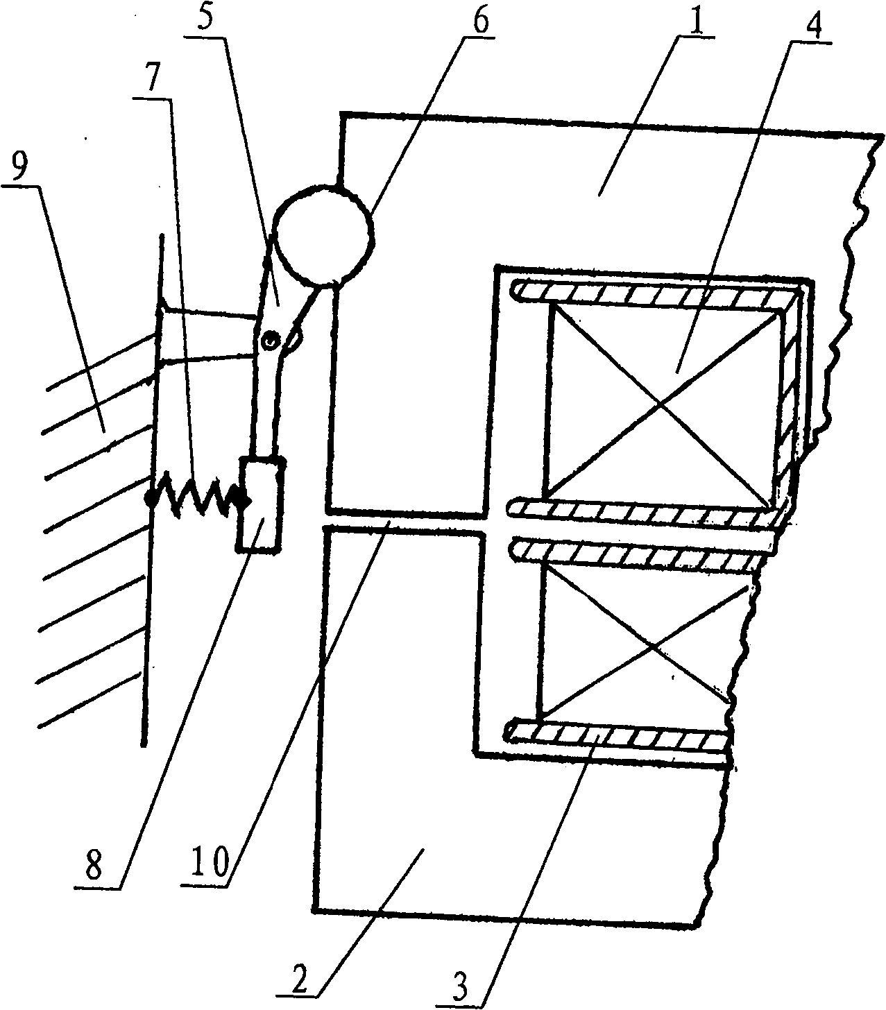
[0015] exist figure 2 In the shown embodiment, a latch 5 with a lever structure is hinged on the housing 9 of the contactor. The middle part of the latch is a hinge shaft...


PUM


Abstract

The invention belongs to a low voltage electrical apparatus and relates to a structure of an electromagnetic contactor, in particular to a non-electric keeping contactor. The invention comprises a magnet comprising a movable core and a fixed core, and the periphery of the core column of the magnet is provided with a coil support which is winded by an electromagnetic coil, a non-electric keeping mechanism is arranged in the contactor shell. The invention is characterized in that the coil support is divided into two separated sections, and that the two sections of coil support are positioned onthe periphery of the movable core and the fixed core respectively, and that the electromagnetic coil is also divided into two groups which winds through the two sections of coil support. The inventionwith simple structure can keep working without electricity and can be cut off conveniently.

Description

technical field [0001] The invention belongs to low-voltage electrical appliances, and relates to a structure of an electromagnetic contactor, in particular to a non-electric holding contactor. Background technique [0002] Ordinary electromagnetic contactors generally include an iron magnet composed of a moving iron core and a static iron core. There is an electromagnetic coil around the core column of the iron magnet. and the static iron core to drive the contacts of the contactor to close. In order to achieve the purpose of the non-electric holding of the electromagnetic contactor to save electric energy, it is necessary to set up a mechanical or permanent magnetic holding mechanism so that the iron core remains in the suction state after the power is cut off. However, at present, there is no suitable structure capable of re-disconnecting the moving iron core and the static iron core in the no-power holding state to overcome the resistance of the holding mechanism, there...

Claims


Application Information

Patent Timeline
Patent Type & Authority Patents(China)
IPC IPC(8): H01H51/10H01H51/01H01H51/12
Inventor 韩天鹏
Owner 韩天鹏
Why Eureka
Eureka Blog
Learn More