Frequency divider

A frequency divider and frequency division technology, which is applied in pulse counters, synchronous pulse counters, counting chain pulse counters, etc., and can solve the problems of complex circuit combination.

Active Publication Date: 2007-07-25
NXP BV
View PDF1 Cites 13 Cited by
  • Summary
  • Abstract
  • Description
  • Claims
  • Application Information

AI Technical Summary

Problems solved by technology

Furthermore, the combinational part of the circuit is relatively complex, and there is no indication for designing other frequency dividers with odd frequency division factors

Method used


Image

  • Frequency divider
  • Frequency divider
  • Frequency divider

Examples


Embodiment Construction

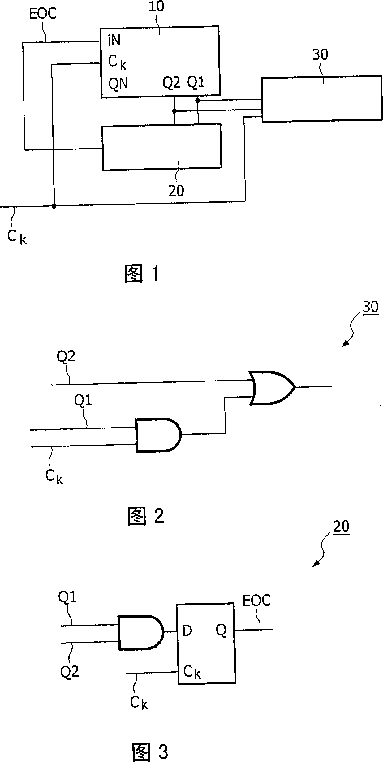
[0024] Fig. 1 shows a block diagram of a frequency divider according to an embodiment of the present invention. The frequency divider providing an odd frequency division factor comprises a binary counter 10 providing an even frequency division factor. This even frequency division factor is obtained by subtracting one from the odd frequency division factor. The binary counter has a clock input for receiving a periodic clock signal Ck having a frequency. The frequency divider also includes an end-of-count circuit 20 connected to the binary counter. The end-of-count circuit 20 generates an end-of-count signal EOC of a cycle of the clock Ck after every even cycle of the clock signal Ck. The count end signal EOC is input to the input terminal IN of the counter 10 . Described frequency divider also comprises the output generator 30 that is connected with binary counter and clock signal Ck, and output generator 30 produces output signal OUT, and the frequency of this signal and odd...


PUM


Abstract

A frequency divider providing an odd integer division factor comprising a binary counter (10) providing an even integer division factor, which is the first even number smaller than the odd division factor, the binary counter having a clock input for receiving a periodical clock signal (Ck) having a frequency. The circuit further comprises an end of count circuit (20) coupled to the binary counter and generating an End Of Count signal (EOC) for a clock (Ck) period after every even integer number periods of the clock signal (Ck), the end of count signal (EOC) being inputted to an input (IN) of the counter (10). The circuit further includes an output generator (30) coupled to the binary counter and to the clock signal (Ck), the output generator (30) generating an output signal (OUT) having a frequency which is substantially equal with the frequency of the frequency signal (Ck) divided by the odd division factor.

Description

technical field [0001] The present invention relates to frequency dividers. Background technique [0002] Frequency dividers are widely distributed in digital devices, and are used to divide an input clock signal and provide an output signal having a frequency-divided clock frequency. The ratio between the frequency of the output signal and the frequency of the input signal (eg, a clock signal) is called a frequency division factor. Usually, the frequency division factor is represented by an integer. [0003] Dividers are relatively simple state machines and can be implemented in various ways. One possible way is to use counters. In this case, the design of the frequency divider is reduced to that of a special counter. There are various known techniques for designing counters, such as described in 'Douglas Lewin, "Design of Logic Systems", Van Nostrand Reinhold (UK) Co. Ltd., 1985, paragraph 6.3. Typically, a frequency divider with a division factor of N is a state mach...

Claims


Application Information

Patent Timeline
Patent Type & Authority Applications(China)
IPC IPC(8): H03K23/50H03K23/54
CPCH03K23/505H03K23/662
Inventor 普拉山特·德凯特多米尼克斯·M·W·利艾特
Owner NXP BV
Why Eureka
Try Eureka