Supercharge Your Innovation With Domain-Expert AI Agents!

Fixing member and mounting structure

A technology for fixing parts and arms, applied in the installation of connecting parts, incandescent lamp parts, coupling devices, etc., can solve the problem that the protruding part 99 cannot be guided to be inserted into the opening 90, etc.

Inactive Publication Date: 2007-08-01
KK TOKAI RIKA DENKI SEISAKUSHO
View PDF6 Cites 6 Cited by
  • Summary
  • Abstract
  • Description
  • Claims
  • Application Information

AI Technical Summary

Problems solved by technology

If the inclination angle θ with respect to the direction perpendicular to the insertion opening 90 becomes too large, the tip of the protrusion 99 comes into contact with the area around the insertion opening 90, so that the protrusion 99 cannot be guided to the insertion opening 90.

Method used


Image

  • Fixing member and mounting structure
  • Fixing member and mounting structure
  • Fixing member and mounting structure

Examples


no. 1 example

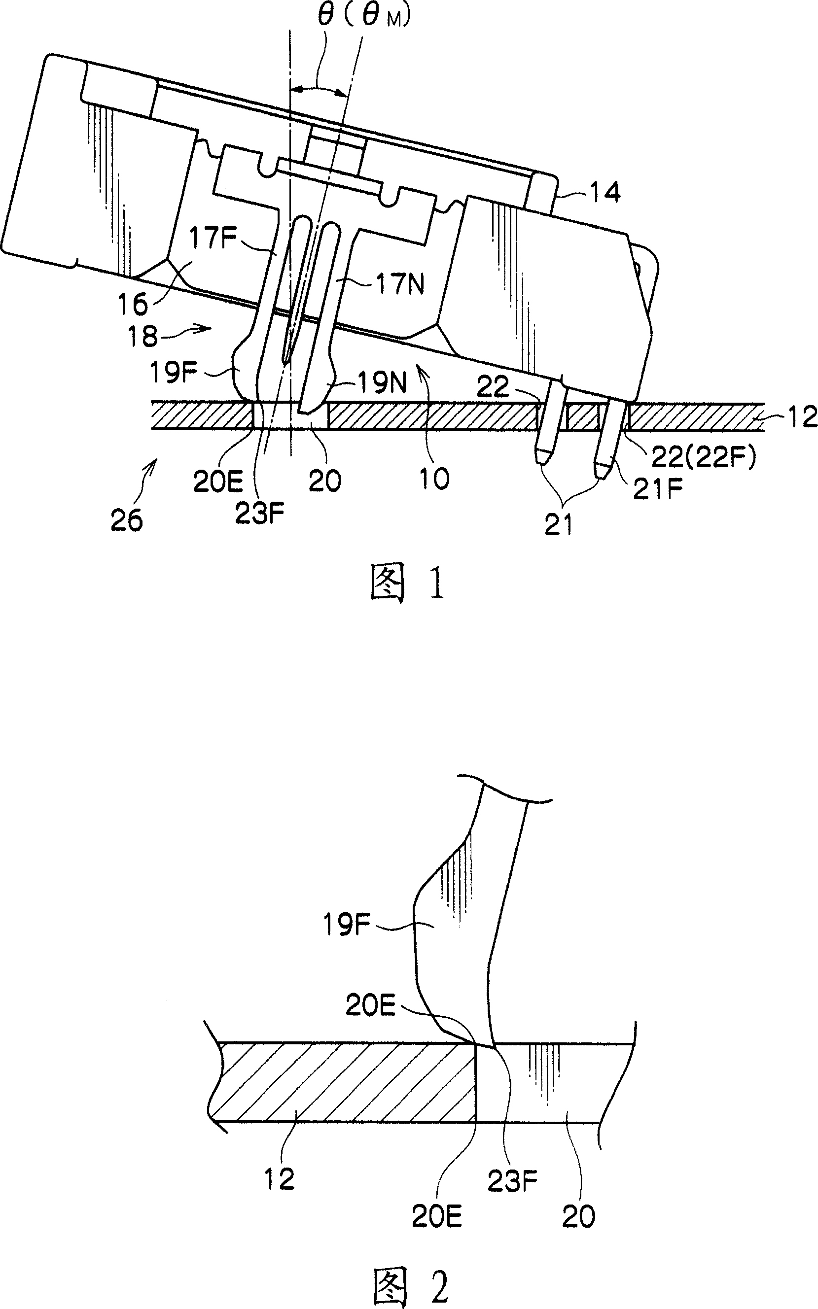
[0028] First, the first embodiment will be described. As shown in FIG. 1 , the fixing member 10 of the present embodiment is a member that can be mounted to an electronic component 14 to be fixed to a printed circuit board 12 .

[0029] The fixing member 10 includes a fixing member body 16 and a male connector portion 18 protruding from the fixing member body 16 , and the male connector portion 18 is a through-hole type connector portion.

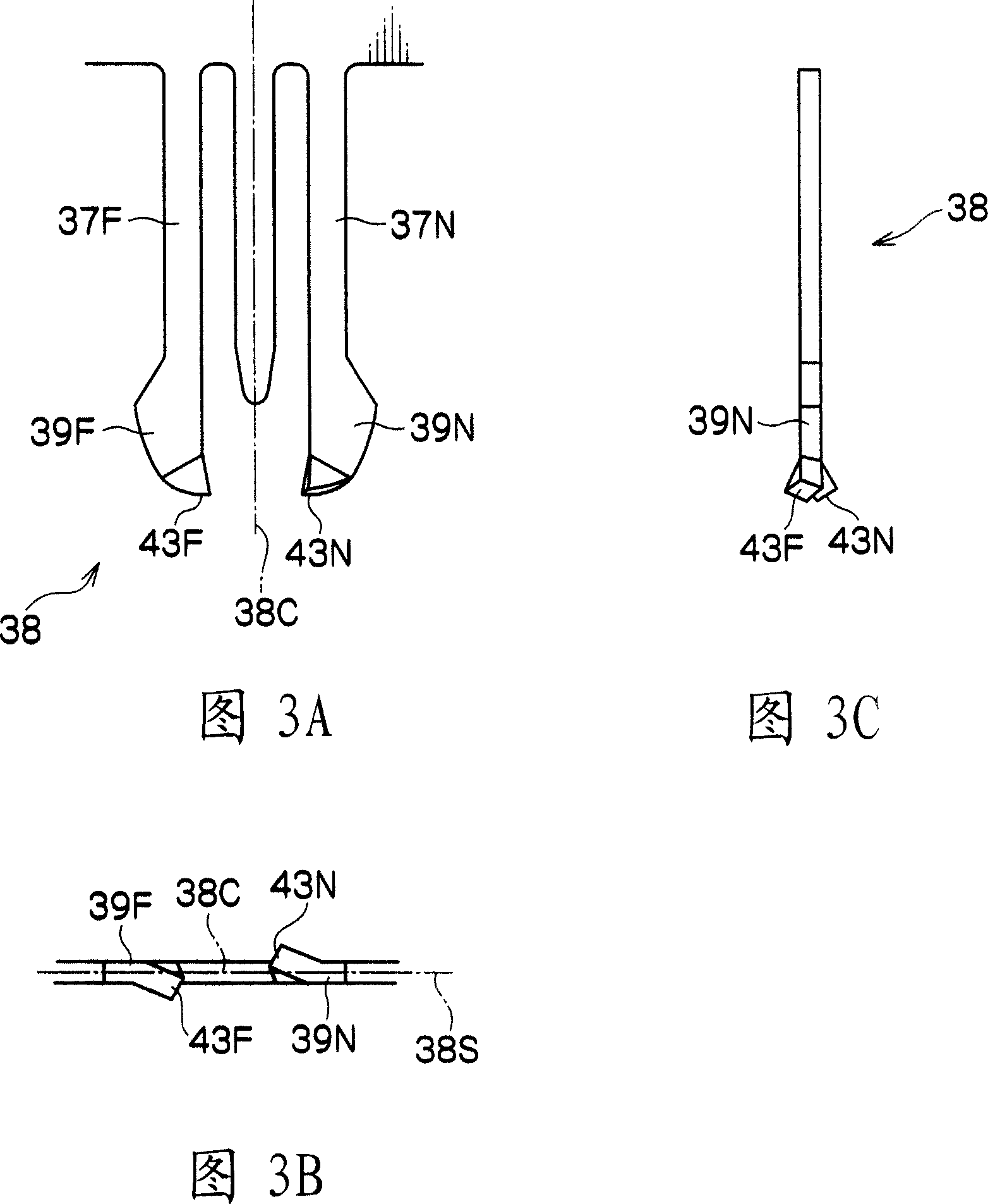
[0030] The male connector part 18 has two arm parts 17F, 17N. The arm portions 17F, 17N are respectively provided at their tip sides with protrusions 19F, 19N to be engaged with the opening edge 20E of the insertion opening 20 formed in the printed circuit board 12 .

[0031] A plurality of terminals 21 protrude from the lower surface side of the electronic component 14 . A plurality of insertion holes 22 are formed in the printed circuit board 12 for insertion of corresponding terminals 21 . In this embodiment, as shown in FIG. 1 , an e...

no. 3 example

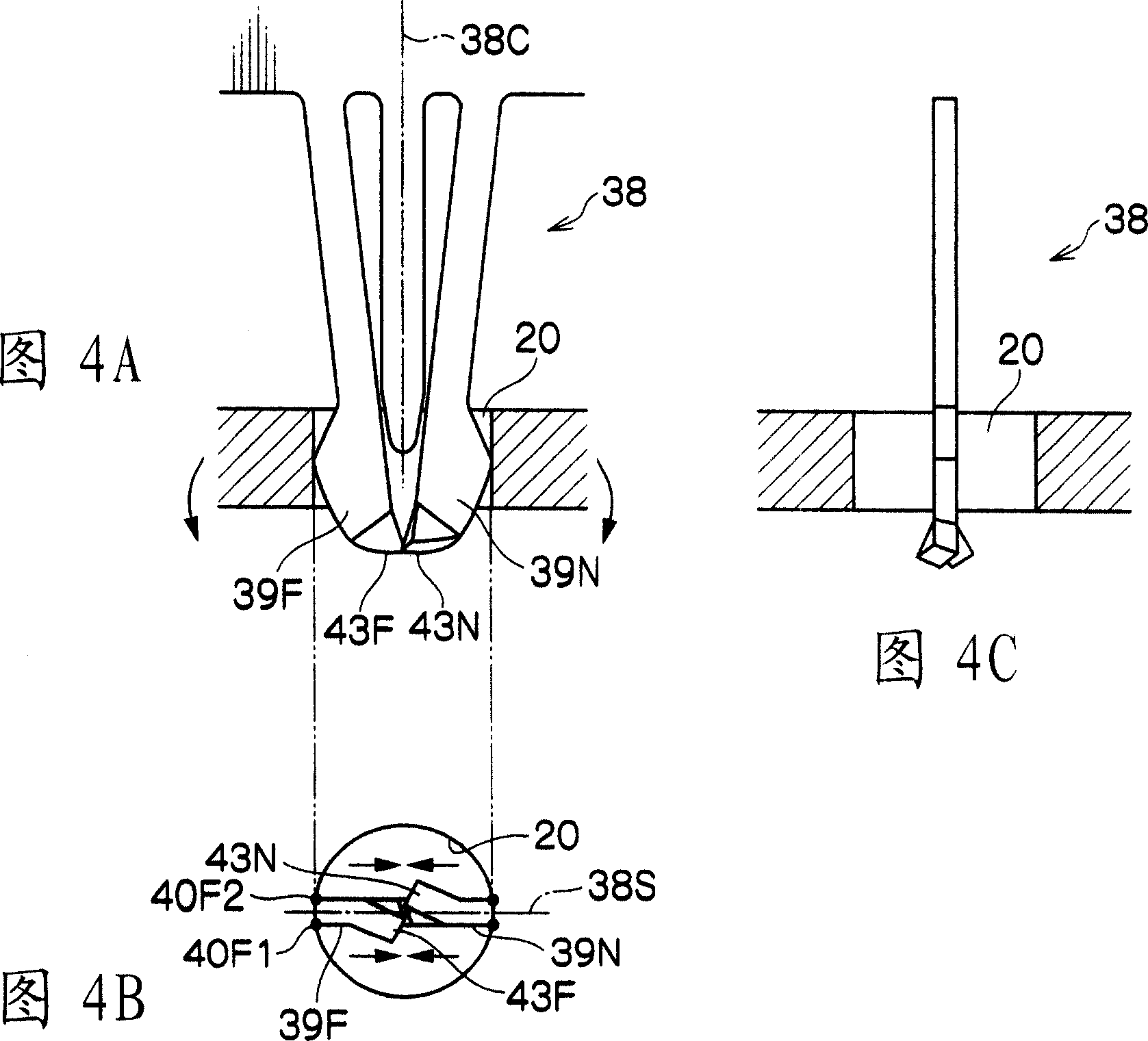
[0049] A third embodiment is described below. As shown in FIGS. 6A to 6C , the fixing member of the present embodiment includes a male connector portion 58 including two arm portions 57F, 57N instead of the two arm portions 17F, 17N of the first embodiment.

[0050] The protrusion 59F of the arm 57F farther from the terminal 21 (see FIG. 1 ) has a protrusion guide 63F, and the protrusion 59N of the arm 57N closer to the terminal 21 also has a protrusion guide 63N.

[0051] In the present embodiment, the dimensions of the protruding guide portions 63F, 63N are set in advance so that the terminal 21 is first inserted into the insertion hole 22 (see FIG. 1 ) to the maximum possible depth and then the male connector portion 58 is inserted toward the insertion opening. When 20 is squeezed, the protrusion guides 63F, 63N come into contact with the opening edge 20E, and the protrusions 59F, 59N are respectively inserted into the insertion opening 20 .

[0052] In addition, in this e...


PUM


Abstract

The invention provides a fixing member and mounting structure. The fixing member of the present invention can be mounted to a fixed member that is fixed to a printed circuit board, and is used for fixing the fixed member to the printed circuit board, the fixing member including: a male connector portion inserted into an insertion opening formed in the printed circuit board; a plurality of arm portions provided at the male connector portion; lug portions provided at each tip end side of the arm portions and engaged with an opening edge of the insertion opening; and a lug-guiding portion extending out from a tip end portion of at least one lug portion to guide the lug portion to the insertion opening when the lug-guiding portion comes in contact with the opening edge and is further pressed.

Description

technical field [0001] The invention relates to a fixing component and a mounting structure, the fixing component can be installed on a fixed component to be fixed on a printed circuit board, and is used for fixing the fixed component to the printed circuit board. Background technique [0002] Many electronic components are mounted on printed circuit boards (PCBs). These electronic components need to be fixed to the printed circuit board, and thus the fixing parts connected with the electronic components are usually fixed to the printed circuit board (for example, refer to Japanese Utility Model Application Publication No. 5-35592, Japanese Patent Application Laid-Open No. 2002- 151191 communiqué, JP-A-11-111407, JP-9-330753, Japanese Utility Model Application Laid-Open No. 5-27969, and JP-2005-310626). A conventional technique will be described below by way of example. [0003] As shown in FIG. 9, conventionally, in order to fix the electronic component 84 to the printed ...

Claims


Application Information

Patent Timeline
Patent Type & Authority Applications(China)
IPC IPC(8): H01R12/22H01R12/32H01R13/74H01R33/74H05K1/18
CPCH01R12/7017
Inventor 高桥伸治加藤义明佐佐木晴英松冈克政南方真人小林浩
Owner KK TOKAI RIKA DENKI SEISAKUSHO
Features
  • R&D
  • Intellectual Property
  • Life Sciences
  • Materials
  • Tech Scout
  • Unparalleled Data Quality
  • Higher Quality Content
  • 60% Fewer Hallucinations
Learn More