Apparatus and method for embedding electronic watermark

一种电子水印、植入装置的技术,应用在电气元件、仪器、计算等方向,能够解决不适用多值图像中间色调、渐变部分等问题

Inactive Publication Date: 2007-08-15
OKI DATA CORP
View PDF1 Cites 2 Cited by
  • Summary
  • Abstract
  • Description
  • Claims
  • Application Information

AI Technical Summary

Problems solved by technology

However, it is not suitable for the same half-tone, gradient parts in multi-valued images

Method used


Image

  • Apparatus and method for embedding electronic watermark
  • Apparatus and method for embedding electronic watermark
  • Apparatus and method for embedding electronic watermark

Examples


no. 1 Embodiment approach

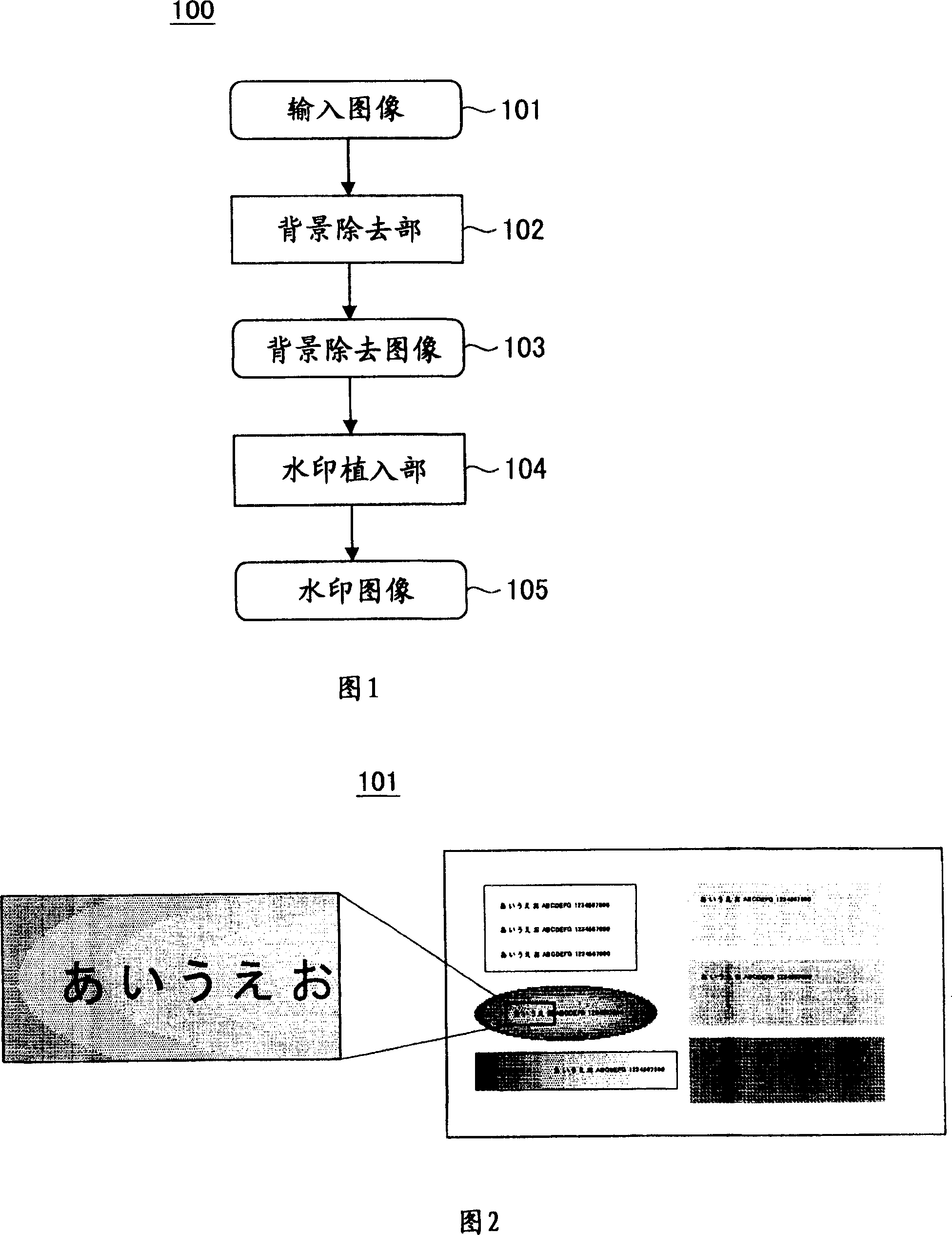
[0046] FIG. 1 is an explanatory diagram showing the structure of the first embodiment.

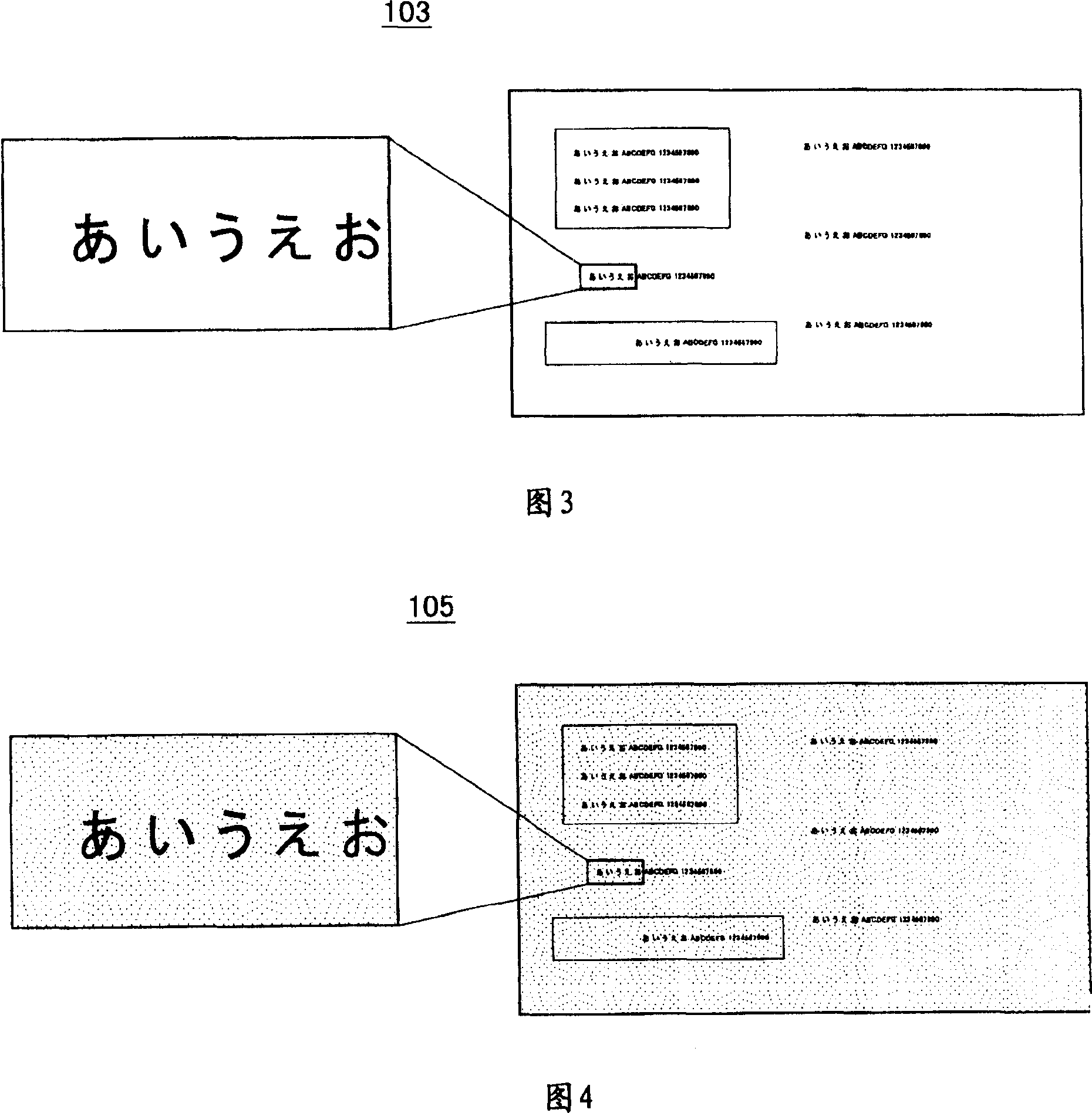
[0047] The digital watermark embedding apparatus 100 of the present embodiment, as shown in FIG. 1 , is configured to include a background removing unit 102 that inputs an input image 101 and removes its background, and a device that inputs a background removed image 103 from which the background is removed and embeds a digital watermark. The watermark embedding unit 104 . The watermark embedding unit 104 outputs a watermark image 105 embedding a digital watermark. Hereinafter, each constituent element will be described in more detail.

[0048] FIG. 2 is an explanatory diagram showing an example of an input image 101 .

[0049] The input image 101 is image data to be watermarked, and is a document image including text, graphics, and photos. As a premise, the input image 101 is a multivalued image. Also, when shadows are added to the input image, an output result in which shadows are re...

no. 2 Embodiment approach

[0086] Hereinafter, a second embodiment of the present invention will be described. The difference of this embodiment is that, when embedding a watermark, the background portion removed in the first embodiment is reproduced using the density expression of the watermark. Hereinafter, description will focus on portions different from those of the first embodiment.

[0087] FIG. 12 is an explanatory diagram showing the structure of the second embodiment. In addition, FIG. 13 and FIG. 14 are explanatory diagrams showing processed images according to this embodiment.

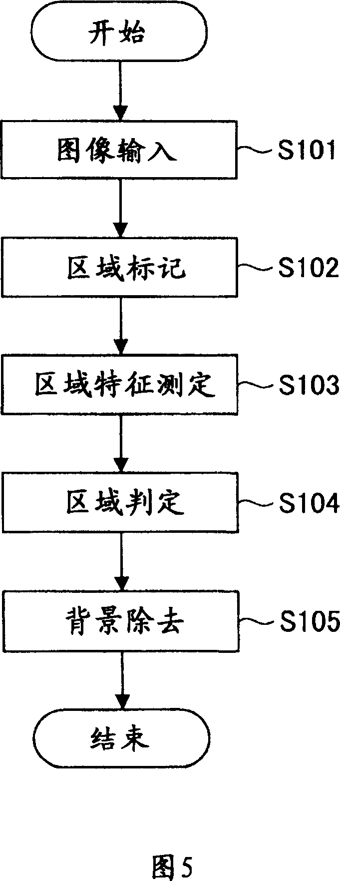
[0088] The background separation unit 201 removes halftone and gradient parts (hereinafter referred to as background parts) other than text and graphic outlines in order to make the watermark easy to embed into the input image 101. A device that outputs the image of the removed background part (background image) separately. Thus, the background separation unit 201 of the present embodiment is a functional unit cor...

no. 3 Embodiment approach

[0100] Next, a third embodiment of the present invention will be described. The difference of this embodiment is that, when the expressible range of density is limited in watermark embedding, only the expressible range is used as the background for separation. In the case of increasing the density level of the watermark based on the dot pattern, it can be realized by increasing the dot diameter or the like as described in the second embodiment, but there is a limit to the increase of the density level that can be read. For example, a density close to total black cannot be read. At density levels above the limit, the watermark reading accuracy decreases, or cannot be read at all. Therefore, it is envisaged that there is a limit to the concentration level of the watermark provided by the watermark implantation device. In this case, in this embodiment, the watermark can be embedded by changing the background separation method.

[0101] Since the structure of this embodiment is...


PUM


Abstract

An electronic watermark embedding apparatus for embedding watermark information as digital information into a document image includes a background eliminating unit that determines whether pixels on an input image are pixels composing a background image and eliminates the pixels determined as the pixels composing the background image from the input image, and a watermark embedding unit that embeds a watermark into a background eliminated image from which the background is eliminated by the background eliminating unit so as to form a watermark image. A readable watermark can be embedded into a multi-valued image including a halftone / gradation portion on the background of the input image.

Description

technical field [0001] The invention relates to an electronic watermark embedding device and an electronic watermark embedding method for embedding information into a document image by using the electronic watermark technology. Background technique [0002] As a technique for embedding information into a document image using a digital watermark technique, there is a technique disclosed in Patent No. 03628312 (Patent Document 1). This document discloses a method in which confidential information and the like can be attached to a document by arranging pixels (dots) on the background of the document by a predetermined method. In this method, since the watermark disappears in the part where the text of the document overlaps with the watermark, the information in this part cannot be read. However, by making the watermark information redundant, correct information can be read as a whole. For example, it can be made redundant by repeatedly embedding dot patterns representing the s...

Claims


Application Information

Patent Timeline
Patent Type & Authority Applications(China)
IPC IPC(8): H04N1/32G06T1/00
CPCH04N1/32256H04N1/32144H04N1/32203G06T1/0028G06T2201/0051H04N1/32235
Inventor 桥本隆志前野蔵人
Owner OKI DATA CORP
Why Eureka
Try Eureka