Oral implant having wing

A technology for oral implants and fins, which is used in dental implants, medical science, dentistry, etc., can solve the problems of long healing period, unstable implantation, insufficient bone height, etc. Healing cycle, effect of increasing contact area

Inactive Publication Date: 2017-12-19
THE AFFILIATED HOSPITAL OF SHANDONG UNIV OF TCM
View PDF6 Cites 4 Cited by
  • Summary
  • Abstract
  • Description
  • Claims
  • Application Information

AI Technical Summary

Problems solved by technology

[0002] At present, dental implant surgery has been fully applied and developed clinically as an effective method for treating and repairing tooth defects or missing teeth. It is often necessary to use various surgical bone augmentation techniques to improve the success rate of implant surgery, especially in the posterior maxillary region, because of the existence of the maxillary sinus, an important physiological structure, in order to avoid the perforation of the sinus floor mucosa during implant surgery. Due to the complications caused by this problem, the maxillary sinus lifting technique came into being. This technique has enabled many patients with insufficient available bone height to be successfully implanted due to the close distance between the maxillary sinus floor and the alveolar crest of the edentulous area. However, the existing columnar implants will directly compress a large area of ​​alveolar bone nerve during implantation, and the healing period is long. At the same time, for patients with weak alveolar bone roots, columnar implants cannot be stably implanted

Method used


Image

  • Oral implant having wing

Examples


Embodiment Construction

[0013] The following will clearly and completely describe the technical solutions in the embodiments of the present invention with reference to the accompanying drawings in the embodiments of the present invention. Obviously, the described embodiments are only some, not all, embodiments of the present invention. Based on the embodiments of the present invention, all other embodiments obtained by persons of ordinary skill in the art without making creative efforts belong to the protection scope of the present invention.

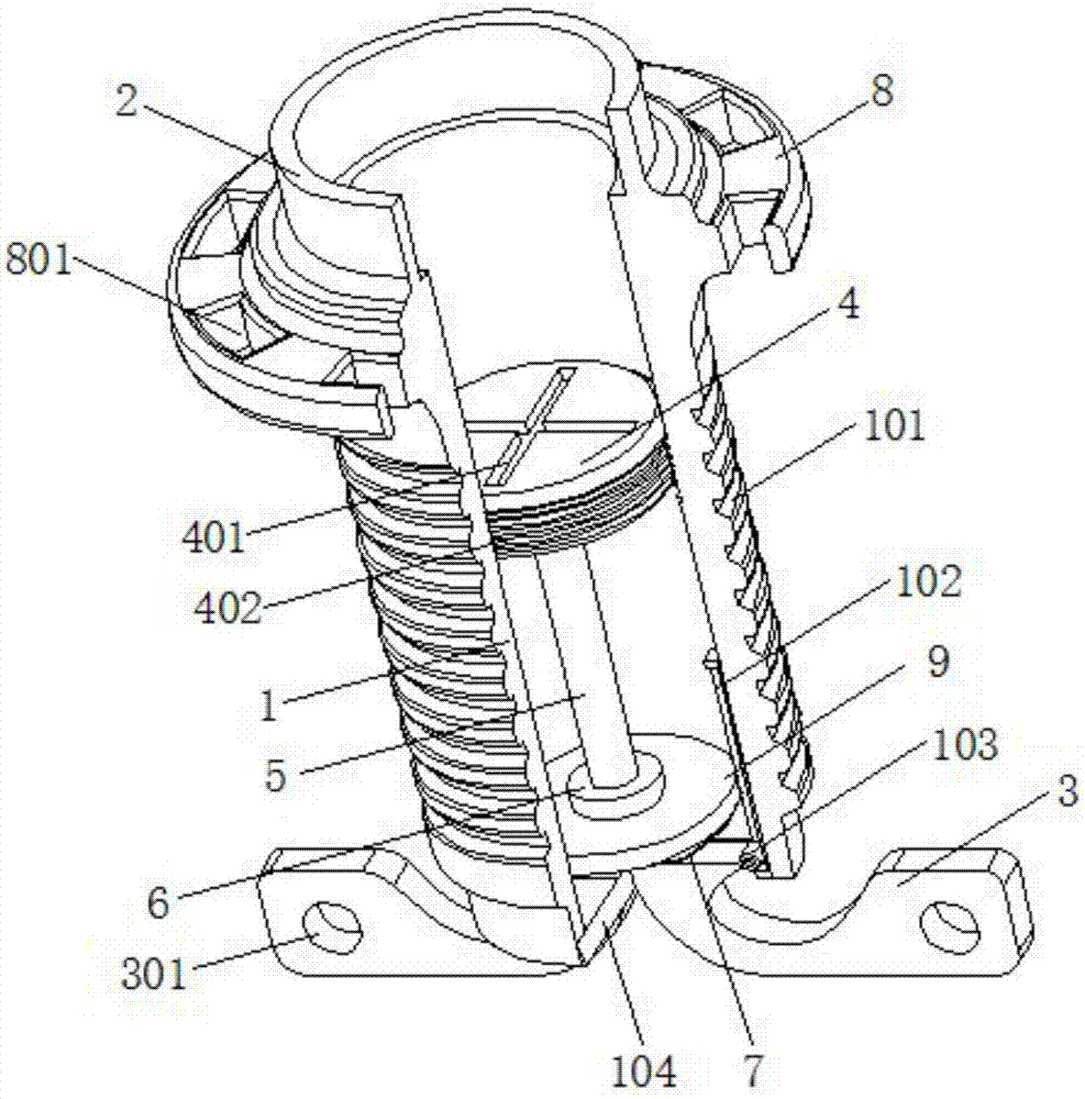
[0014] see figure 1 , the present invention provides a technical solution: a dental implant with fins, comprising an implant 1, an annular wing plate 8 is arranged on the outer surface of the upper end of the implant body 1, and the middle part of the wing plate 8 is evenly distributed with The through groove 802, the outer side of the upper end of the implant 1 is provided with a wing plate 8, which increases the contact area with the upper surface of the alv...


PUM


Abstract

The invention discloses an oral implant having wing. The oral implant comprises an implantation material, the implantation material is a hollow shell with two opened ends, the external thread is arranged at the central section at the side surface of the implantation material, an annular basic bench is fixed at an upper opened end of the implantation material, the chutes are oppositely arranged at the inner side surface of the lower end of the implantation material, the oral implant has a simple structure, a traditional cylindrical implantation material is used for integral body support, the external thread realizes stable occlusion with alveolar bone, a wing plate is arranged at the outside of the upper end of the implantation material, the contact area of the alveolar bone and the wing plate is increased, the chute is convenient for consilience with the alveolar bone after growth, the longitudinal stability is guaranteed, the total length of the implantation material is reduced, the transverse stability of the implantation material is realized by a stabilization sheet, contraction of the implantation material is realized, and the implantation of the implantation material is not influenced, contact and compressing of the implantation material and nerve at the bottom of the alveolar bone is greatly reduced, a healing period is shortened, the occupation space is small, the oral implant is suitable for weak root of the alveolar bone for the patients, and the implantation and the dismounting are convenient.

Description

technical field [0001] The invention relates to the technical field of oral cavity treatment, in particular to an oral cavity implant with wings. Background technique [0002] At present, dental implant surgery has been fully applied and developed clinically as an effective method for treating and repairing tooth defects or missing teeth. It is often necessary to use various surgical bone augmentation techniques to improve the success rate of implant surgery, especially in the posterior maxillary region, because of the existence of the maxillary sinus, an important physiological structure, in order to avoid the perforation of the sinus floor mucosa during implant surgery. Due to the complications caused by this problem, the maxillary sinus lifting technique came into being. This technique has enabled many patients with insufficient available bone height to be successfully implanted due to the close distance between the maxillary sinus floor and the alveolar crest of the eden...

Claims


Application Information

Patent Timeline
Patent Type & Authority Applications(China)
IPC IPC(8): A61C8/00
CPCA61C8/0031A61C8/0039
Inventor 谢涌涛
Owner THE AFFILIATED HOSPITAL OF SHANDONG UNIV OF TCM
Why Eureka
Try Eureka