Menstrual cup

A menstrual and cup handle technology, applied in the field of menstrual cups, can solve the problems of lack, disinfection, and inability to boil

Inactive Publication Date: 2007-09-05
DIVA INT INC
View PDF3 Cites 13 Cited by
  • Summary
  • Abstract
  • Description
  • Claims
  • Application Information

AI Technical Summary

Problems solved by technology

Furthermore, known cups generally lack a convenient and easy gripping portion at their bottom end to facilitate removal of the cup
Finally, known cups are usually made of thermoplastics such as polyethylene, which, despite their corresponding flexibility and elasticity, cannot be boiled to sterilize them
Alternatively, known cups can be made from natural latex rubber, however, this material has the disadvantage that many users are severely allergic to it

Method used


Image

  • Menstrual cup
  • Menstrual cup
  • Menstrual cup

Examples


Embodiment Construction

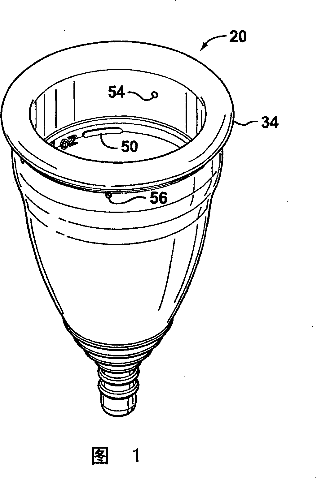
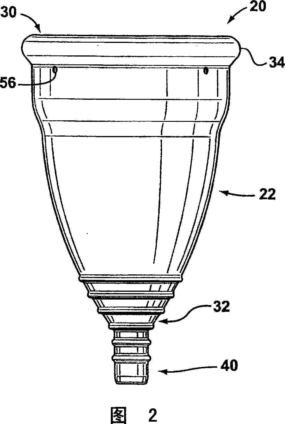
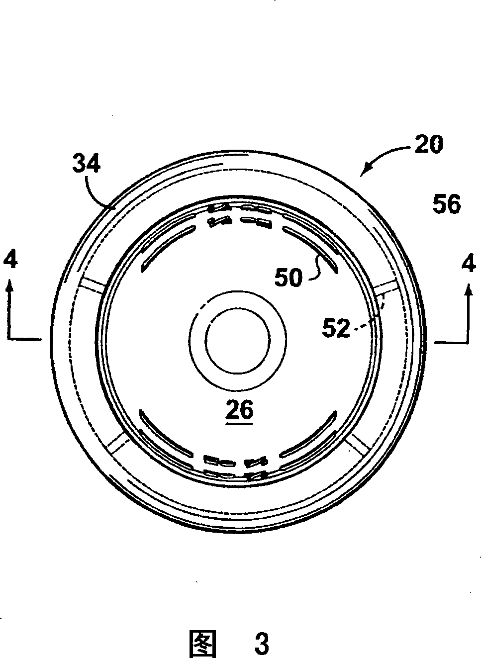
[0016] Referring first to FIG. 4 , a preferred embodiment of a cup according to the present invention, indicated generally by the numeral 20 , is described. A cup 20 suitable for use in the vagina (not shown) includes a container 22 having a wall 25 with an inner wall surface 24 defining a cavity 26 adapted to collect fluid (not shown) and in contact with the inner wall surface. 24 opposite the outer wall surface 28. The container 22 extends from an open top end 30 to a closed bottom end 32 . Tip 30 preferably has a predetermined outer diameter (indicated as "D" in FIG. 4 ), and container 22 is flexible and resilient, as described below. Wall 25 includes an upper rim portion 34 that reinforces tip 30 and maintains cup 20 in a preselected position (not shown) within the vagina. Additionally, wall 25 includes a body portion 36 extending from bottom end 32 to top end 30 . Wall 25 additionally includes a transition portion 38 between main body portion 36 and upper rim portion 3...


PUM


Abstract

A menstrual cup for use in a vagina. The cup includes a receptacle extending from an open top end to a closed bottom end and a stem attached to the receptacle at the bottom end thereof, for use in removal of the cup. The receptacle comprises a wall having an inner wall surface defining a cavity adapted for collecting fluid and an opposed outer wall surface. The open top end has a predetermined diameter, the receptacle being adapted to be flexible and resilient. The outer wall surface includes an upper rim at the top end of the receptacle for strengthening the top end, a main portion extending from the bottom end of the receptacle portion towards the top end, and a transition portion between the main portion and the upper rim, the transition portion being streamlined to define a profile thereof which is substantially smooth.

Description

technical field [0001] The present invention relates to menstrual cups. Background technique [0002] Menstrual cups are known and described in US Patent Nos. 1,891,761 (Goddard), 1,996,242 (Hagedorn), 2,089,113 (Chalmers) and in US Design Patents Des. 323,212 (Crawford) and Des. 5,827,248 (Crawford) Various cups are disclosed. [0003] However, known menstrual cups have several disadvantages. For example, typical cups include a steeply profiled ridge, generally located near an upper portion thereof, which tends to hinder removal of the cup. While this steeply profiled ridge can help secure the cup in place, the ridge tends to hinder removal of the cup, sometimes causing discomfort. Also, known cups may include a plurality of holes disposed proximate to the ridge, which facilitate insertion and removal of the cup by equalizing the air pressure inside and outside the cup as the cup is inserted and removed. Furthermore, known cups generally lack a convenient and easy gripp...

Claims


Application Information

Patent Timeline
Patent Type & Authority Applications(China)
IPC IPC(8): A61F5/455
CPCA61F6/08A61F5/4553
Inventor C·钱伯斯F·钱伯斯
Owner DIVA INT INC
Why Eureka
Try Eureka