Bridging tap device

A faucet and bridging technology, used in valve devices, water supply devices, indoor sanitary pipeline devices, etc.

Inactive Publication Date: 2007-11-21
NEWFREY
View PDF0 Cites 3 Cited by
  • Summary
  • Abstract
  • Description
  • Claims
  • Application Information

AI Technical Summary

Problems solved by technology

Such a mechanism makes it difficult to supply water to the hose portion of the pull-out faucet spray or side spray

Method used


Image

  • Bridging tap device
  • Bridging tap device

Examples


Embodiment Construction

[0011] Detailed Description of Preferred Embodiments

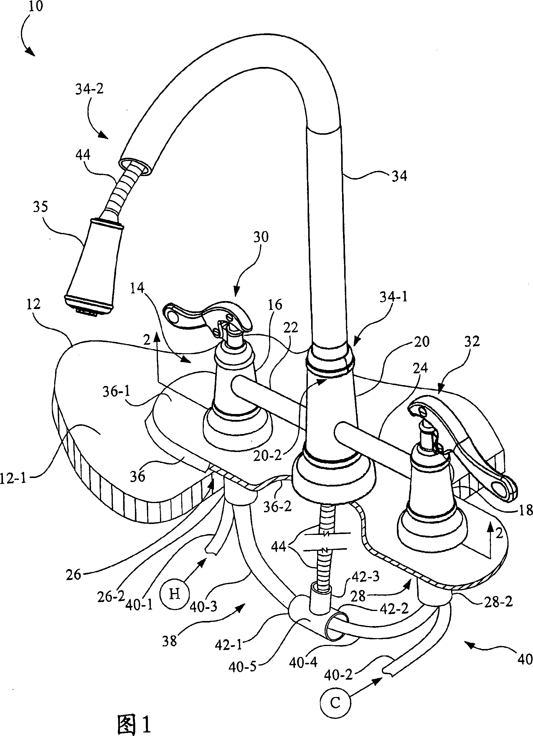
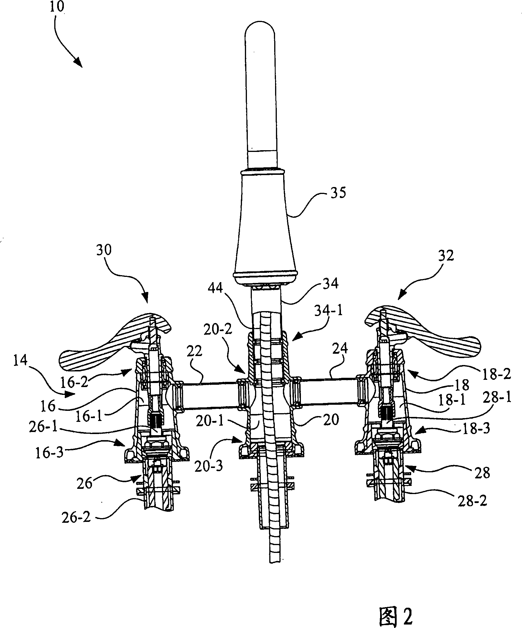
[0012] Referring now to the drawings and in particular to FIG. 1 , there is shown a bridging faucet assembly 10 constructed in accordance with an embodiment of the present invention. The bridging faucet device 10 is installed on a mounting surface such as a work surface 12, and the work surface is formed with a mounting surface 12-1. Other examples of mounting surfaces include, but are not limited to, countertops, walls, and sinks, among others. Most of the countertop 12 has been cut away to more clearly show the structure of the bridge faucet assembly 10 .

[0013] The bridge faucet assembly 10 includes a one-piece non-liquid base. The non-liquid base 14 is formed with a first end body 16 , a second end body 18 , a spout riser 20 , a first non-liquid carrier 22 and a second non-liquid carrier 24 . The first non-liquid carrier 22 is arranged as a cross piece and is suspended and connected between the first end body 16 a...


PUM


Abstract

A faucet assembly includes a unitary non-fluidic body defined by a first end body, a second end body, a spout riser, a first non-fluid carrying support member, and a second non-fluid carrying support member. The first non-fluid carrying support member is suspended between the first end body and the spout riser, and the second non-fluid carrying support member is suspended between the second end body and the spout riser.

Description

technical field [0001] The invention relates to a faucet, in particular to a bridging faucet device. Background technique [0002] A faucet typically includes a spout with a spray head connected via a fluid line to a pair of hot and cold water valves. Valve operating mechanisms such as handles are respectively connected to the above-mentioned hot and cold water valves, and the above-mentioned valves are operated by manual rotation of the valve operating mechanisms in sequence. A well-known example is the bridge tap. [0003] The bridging faucet in the prior art supplies cold and hot water from the terminal mechanism to the spout riser on the installation surface such as the countertop and worktop. Such a mechanism makes it difficult to supply water to the hose portion of the pull-out faucet spray or side spray. Contents of the invention [0004] One aspect of the invention is directed to a faucet. The faucet device includes an integral non-liquid base body composed of ...

Claims


Application Information

Patent Timeline
Patent Type & Authority Applications(China)
IPC IPC(8): F16K27/00F16K11/22
CPCY10T137/87684E03C1/04E03C2001/0415
Inventor 阿尔斯通·E·威廉斯戴维·R·唐尼
Owner NEWFREY
Why Eureka
Try Eureka