
Profiling comb

A profiling and comb-like technology, applied in the field of profiling combs, can solve the problems of low precision, cumbersome operation process, low efficiency, etc., and achieve the effect of increasing the friction coefficient

Inactive Publication Date: 2007-11-21
CHONGQING LIFAN INDUSTRIAL (GROUP) CO LTD
View PDF0 Cites 0 Cited by
  • Summary
  • Abstract
  • Description
  • Claims
  • Application Information

AI Technical Summary

Problems solved by technology

Because this kind of operation mainly depends on the subjective judgment of the operator, it is cumbersome, inefficient and accurate in the operation process.

Method used


Image

  • Profiling comb
  • Profiling comb
  • Profiling comb

Examples


Embodiment Construction

[0014] Below in conjunction with accompanying drawing and embodiment the present invention will be further described:

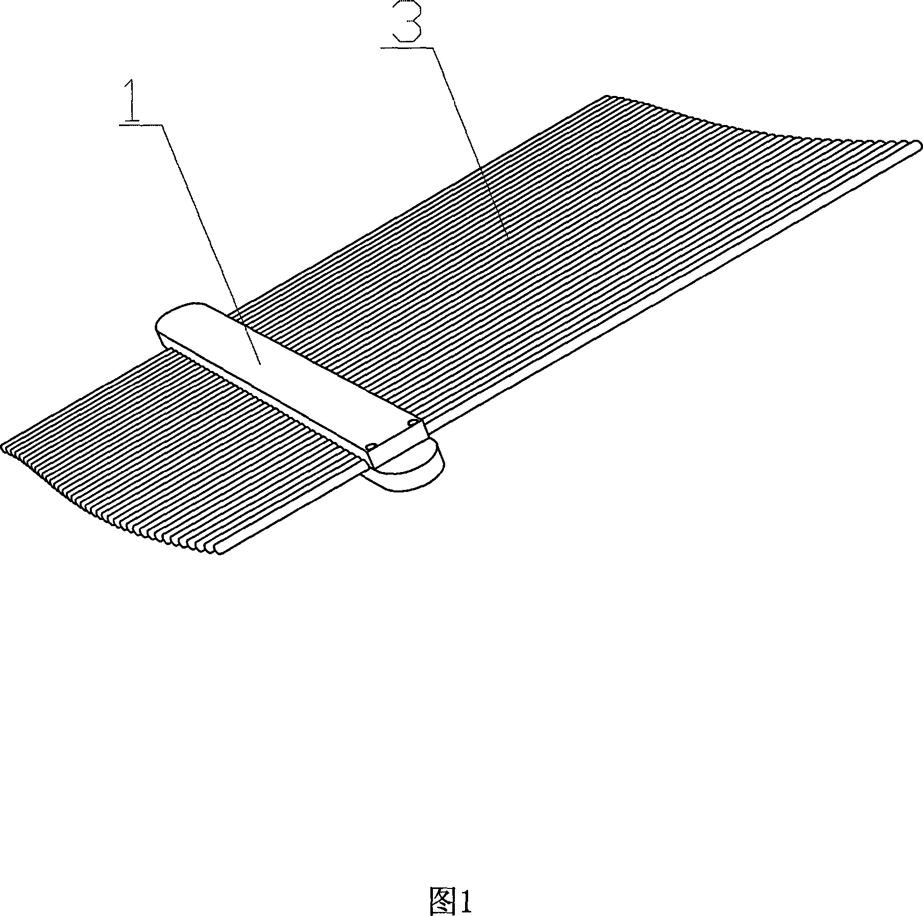
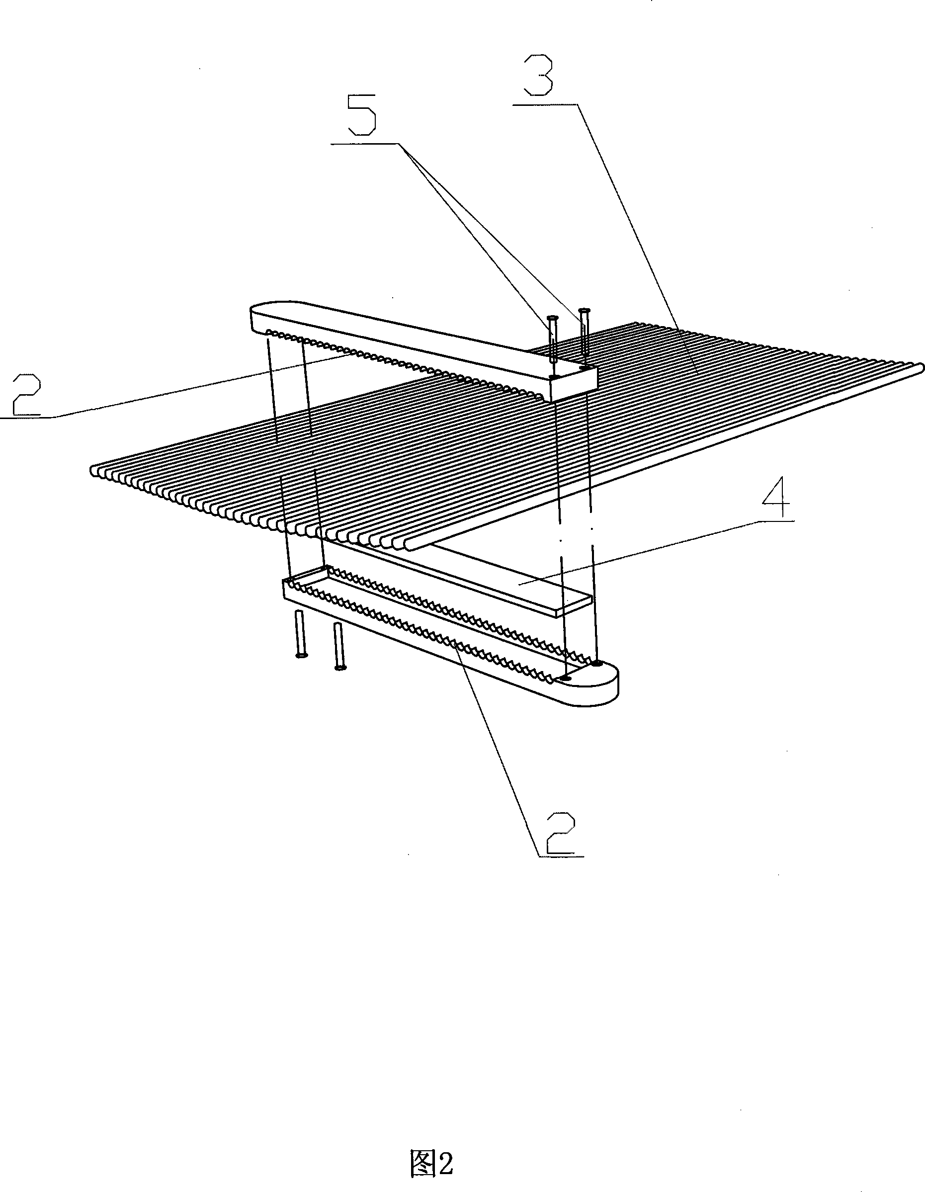
[0015] Embodiment, as shown in Fig. 1, 2: the present invention is mainly made up of profiling clip 1, profiling needle 3, damping sheet 4, and wherein profiling clip 1 is made up of upper and lower two clip bars, and described two clip bars It is a groove-shaped strip, and the top edge of the groove is evenly and continuously distributed with needle pockets 2, the upper and lower clips are butted to make the needle pockets 2 close up to form pinholes, and the profiling needles 3 are inserted into the pinholes to form a "comb shape", There is clearance fit between the profiling needle 3 and the pinhole, and a damping sheet 4 is arranged between the clip bar of the profiling clip 1 and the "comb-shaped" profiling needle 3 .

[0016] In the present embodiment, the two clip bars of the profiling clip have mounting holes at both ends, and the screws 5 pass throug...


PUM


Abstract

A contour comb is prepared as forming contour clamp by top and bottom clamp strips with needle sockets, butt-jointing two said clamp to form needle holes by needle sockets on two said clamps, inserting contour needle into formed holes to make comb shape, arranging gas coordination between contour needle and needle hole and setting thin damping plate between contour clamp strip and comb-shaped contour needle.

Description

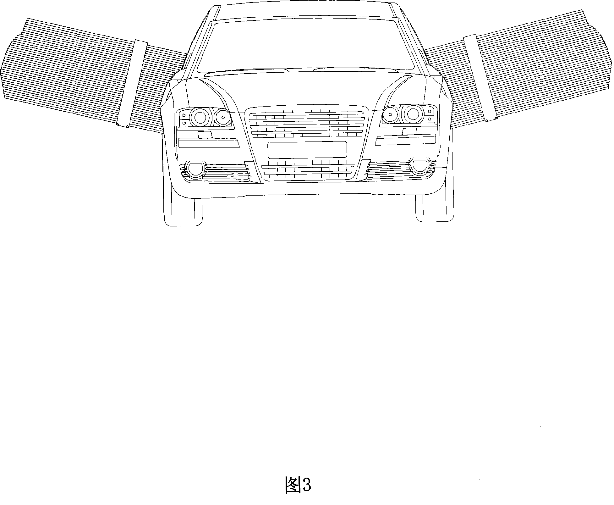
technical field [0001] The invention belongs to the field of measuring tools, in particular to a profiling comb for measuring special-shaped curved surfaces. Background technique [0002] In the design and manufacture of automobiles and other mechanical fields, the designed drawings and three-dimensional shapes are often made to reflect the real situation by making 1:1 clay models. In particular, it is convenient to observe the entire shape actually manufactured in order to make corresponding improvements. Since the clay model is almost made by hand, it is often difficult to ensure that the produced model is exactly the same as the designed drawing in the production project, and there will always be certain differences. Especially for larger objects like cars, the left-right asymmetry of the outer surface often occurs. In order to ensure that the left and right sides of the car are as symmetrical as possible when making the clay model, the usual practice is: take the criss...

Claims


Application Information

Patent Timeline
Patent Type & Authority Applications(China)
IPC IPC(8): G01B5/20
Inventor 李洲荣冯平
Owner CHONGQING LIFAN INDUSTRIAL (GROUP) CO LTD
Learn More