
Tooth element for a removing roller

A technology of toothed components and components, applied in the direction of unpacking with toothed tools, etc., can solve the problems of lack of stability, reducing the cleaning effect of toothed components, and blunt tooth tips.

Inactive Publication Date: 2007-11-21
MASCHINENFABRIK RIETER AG
View PDF1 Cites 0 Cited by
  • Summary
  • Abstract
  • Description
  • Claims
  • Application Information

AI Technical Summary

Problems solved by technology

[0004] A prominent disadvantage of the disclosed toothed member is its lack of stability when the protruding teeth are inserted into a stably compressed fibrous material
[0005] Another disadvantage is that in the case of teeth made of thin steel, the tips of the teeth can become dull quickly
In this case, the cleaning effect of the toothed elements is reduced and in particular the size of the opened fiber bundles becomes inhomogeneous
Rapid wear of the tooth tips can be counteracted by coating in the tooth tip area, but this does not completely prevent wear

Method used


Image

  • Tooth element for a removing roller
  • Tooth element for a removing roller
  • Tooth element for a removing roller

Examples


Embodiment Construction

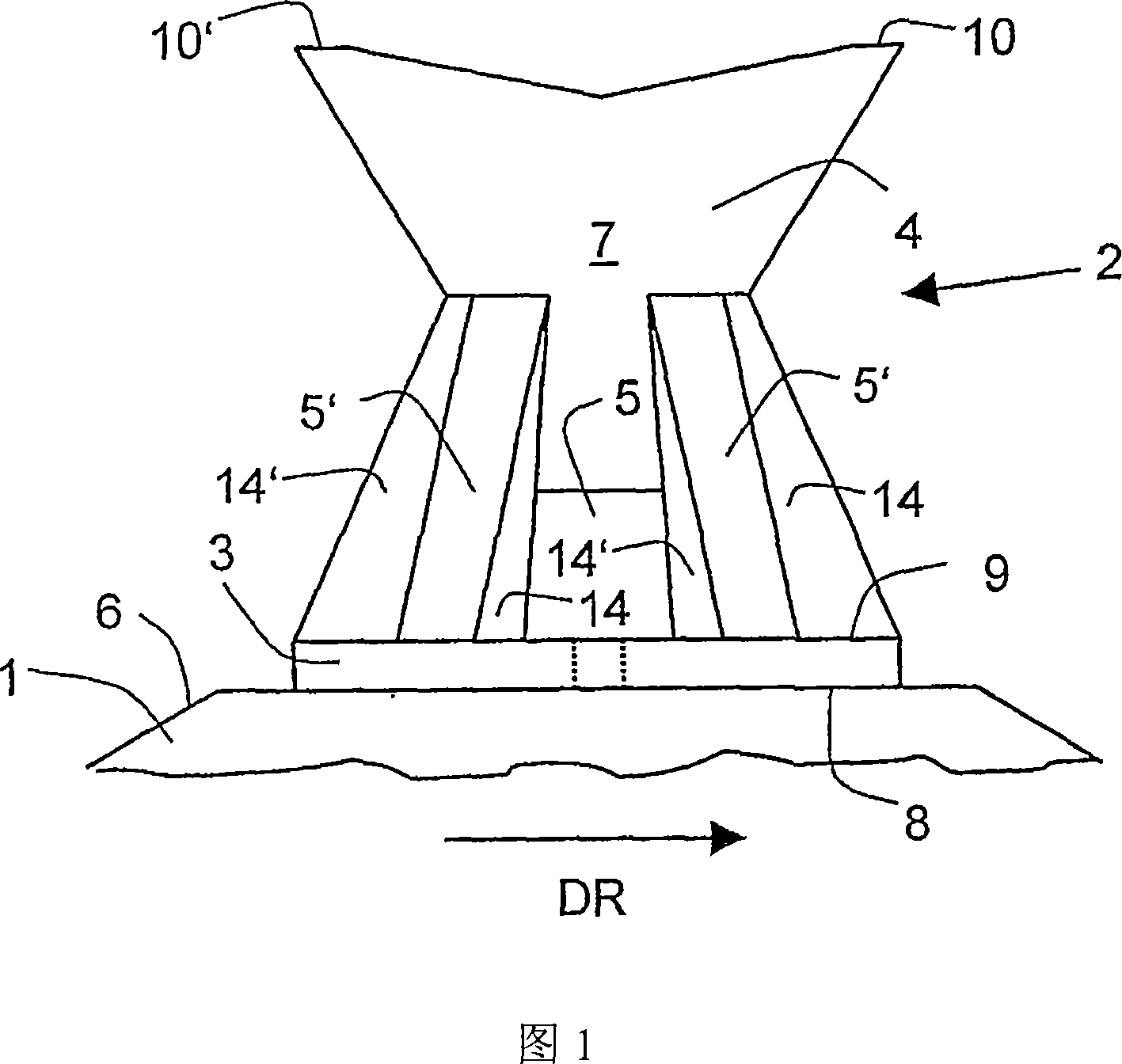
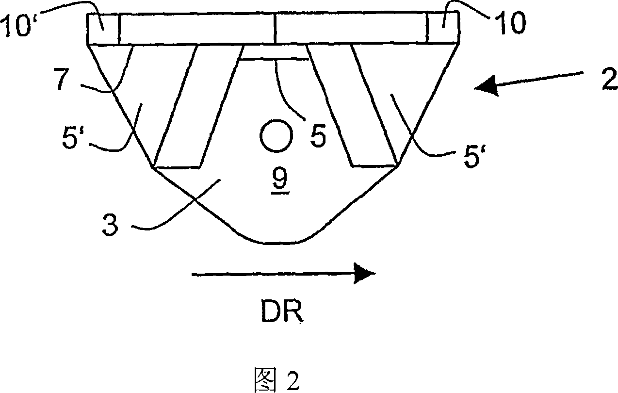
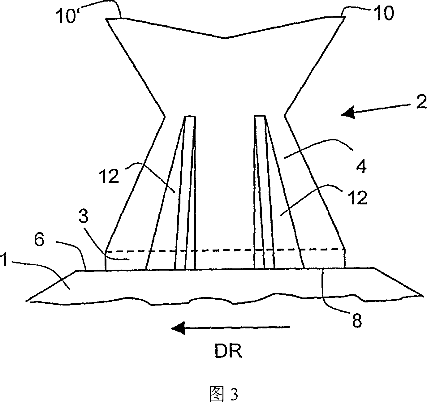
[0028] Figure 1 shows a toothed member according to the invention comprising a support 3 and teeth 4 arranged thereon. The tooth 4 has a tooth tip 10 pointing in the direction of rotation 10 and a tooth tip 10 ′ pointing in the opposite direction. The support has a flat underside and can therefore match the dodecagonal circumferential contour 6 of the removal roller 1 . FIG. 1 shows only one side of the roller 1 . In total, the roller 1 has a plurality of toothed elements 2 which are arranged on each side and are radially offset. However, since other toothed members have the same structure as the toothed member 2, only the toothed member 2 will be described in this specification. The transverse struts 5 and 5 ′ are arranged between the lateral flank socket 7 of the tooth and the upper side of the support 9 . The central transverse strut extends in the edge region between side 9 and side 7 , which forms a wedge shape. Its height extends approximately over a quarter of the h...


PUM


Abstract

The invention relates to a tooth element for a removing roller (1) of a bale opener. Said tooth element comprises a plate-shaped support (3) whose bottom face is adapted to the circumferential contour of the removing roller, and at least one first tooth (4) that is embodied in a plate-shaped manner and is disposed at an angle on the support.

Description

technical field [0001] The invention relates to a toothed member for a removal roller of a bale opener, comprising a disc-shaped support, the bottom surface of which fits the circumferential profile of the removal roller; and at least one first tooth, which is configured in a disc-shaped manner and Set at an angle to the support. Background technique [0002] From EP0928839 is known a device for removing lint comprising a plurality of toothed members. This removal roller comprises, as a base, a polygonal tube to which said toothed members are fixed in an exchangeable manner. The toothed member comprises a support whose bottom side fits the profile of the polygonal roller, which has a kinkled crossbeam along its circumferential running direction, so that the support has two flat surfaces, which in turn can be fixed to the polygonal roller, And be able to surround the corner of the roller. Disc-shaped teeth are disposed on each flat surface of the support at an angle to tha...

Claims


Application Information

Patent Timeline
Patent Type & Authority Applications(China)
IPC IPC(8): D01G7/04
CPCD01G7/04
Inventor 瓦尔特・施勒普费尔西蒙・海尼格格茨・特奥多尔・格雷塞尔
Owner MASCHINENFABRIK RIETER AG
Learn More