
Droplet deposition apparatus

A deposition device and droplet technology, applied in printing and other directions, can solve problems such as reducing the speed of sprayed droplets

Inactive Publication Date: 2008-01-16
XAAR TECH LTD
View PDF2 Cites 12 Cited by
  • Summary
  • Abstract
  • Description
  • Claims
  • Application Information

AI Technical Summary

Problems solved by technology

However, because each wall acts on both chambers simultaneously, it is impossible to eject droplets from each ejection chamber at the same time, thus reducing the velocity of ejected droplets

Method used


Image

  • Droplet deposition apparatus
  • Droplet deposition apparatus
  • Droplet deposition apparatus

Examples


Embodiment Construction

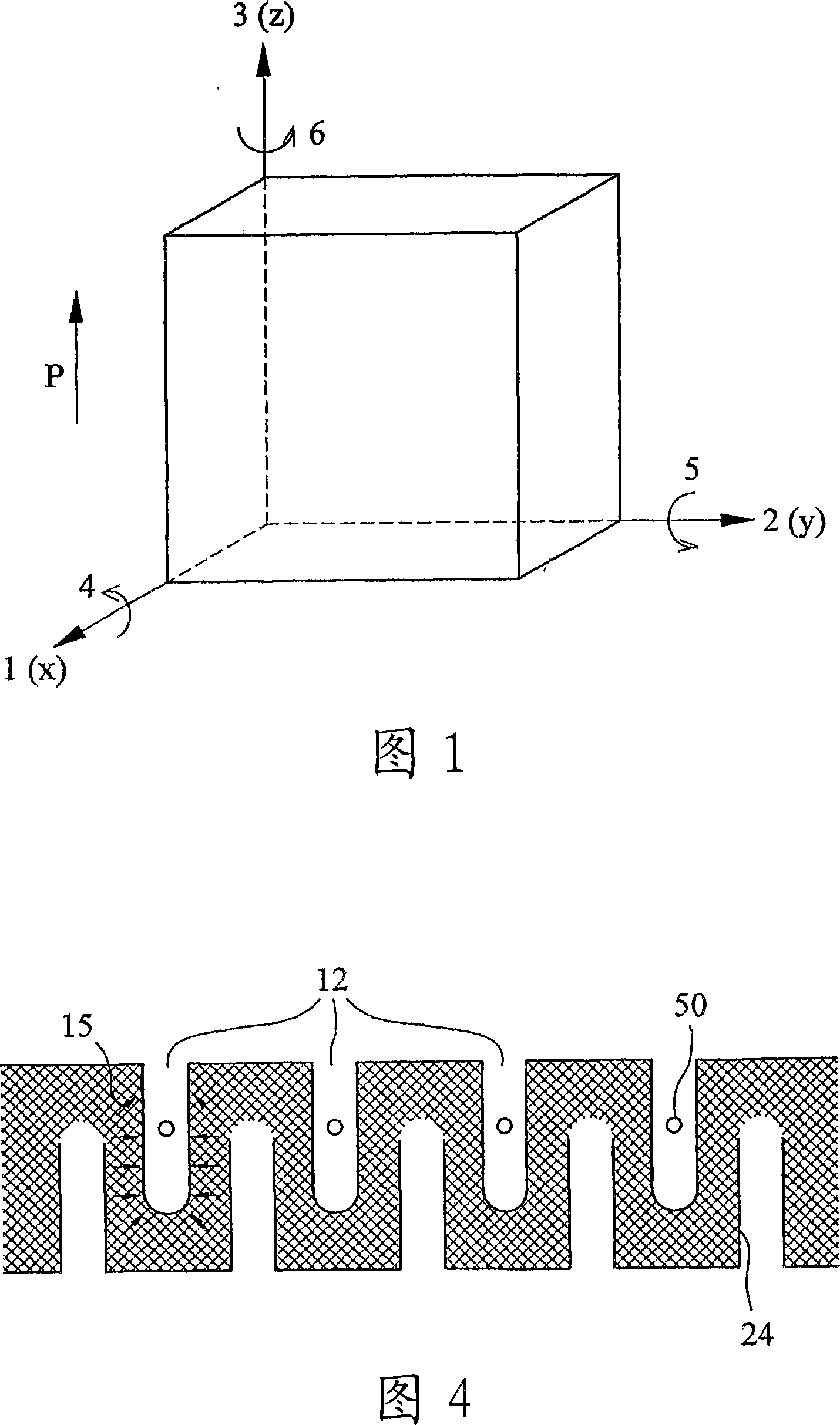
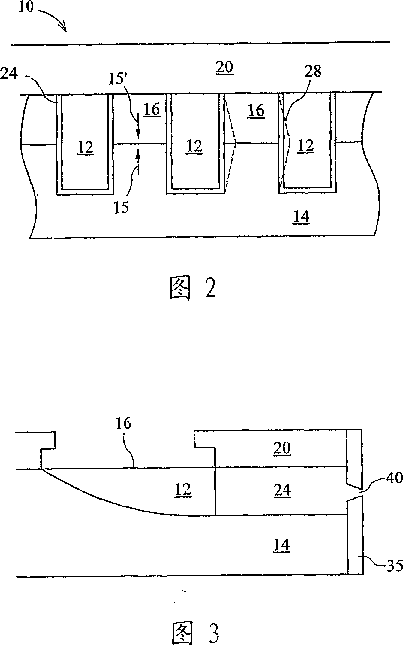
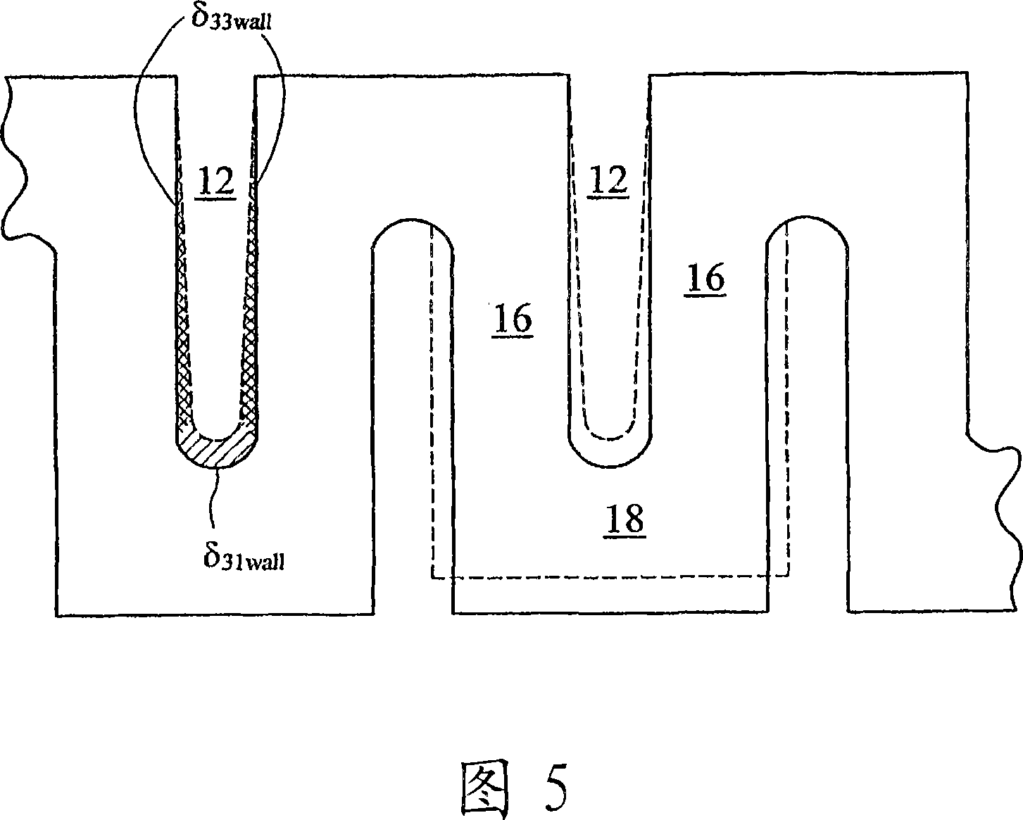
[0035]Referring to Figure 2, the ink jet printhead 10 includes a plurality of parallel ink channels 12 forming an array in which the channels are spaced from each other in an array direction perpendicular to the length of the channels. Said channels are formed at a density of two or more channels per mm in a laminate 14 made of piezoelectric material, suitably PZT, which is polarized in the direction of arrows 15, 15'. , and each channel is defined by sidewalls 16 and a bottom surface, the thickness of the PZT is greater than the depth of the channel. The channel 12 is open at the top and closed in the print head by a top sheet 20 of insulating material thermally mated to the sheet 14 and arranged parallel to the bottom surface of the channel and bonded to the top 22 of the wall 16 . The channels 12 are lined with metallized electrode layers 24 on their sidewalls and bottom surfaces. Thus, when a potential difference of similar magnitude but opposite sign is applied to the el...


PUM


Abstract

An actuator taking the form of a piezoelectric wall separating two chambers, which utilises two actuation modes. Both actuation modes cause volume displacements in both chambers, but act to reinforce one another in one chamber and cancel one another in the other chamber. A fluid pump for droplet deposition having an array of channels separated by such actuators can be operated with each channel acting substantially independently of its neighbours.

Description

technical field [0001] The present invention relates to actuators, and in particular to actuators for droplet deposition devices. Background technique [0002] Droplet deposition devices or inkjet printheads can place small fluidic droplets onto a substrate. This device (hereafter referred to as an inkjet printhead, although the device is also capable of ejecting fluids other than ink) forces the fluid out of nozzles in communication with the ejection chamber. An actuator corresponding to the ejection chamber applies a force to eject the fluid. These actuators take many different forms, but tend to fall into one of two categories. The first of the two categories is mechanical, in which electrical pulses deform the actuator, and the first category includes, for example, techniques such as electrostatic, thermal bending, or piezoelectric. The second category is thermal or bubble actuators, where heat is applied to bring the fluid to its nucleation point. The resulting air ...

Claims


Application Information

Patent Timeline
Patent Type & Authority Applications(China)
IPC IPC(8): B41J2/14B41J2/16
CPCB41J2/14209B41J2/164B41J2/1609B41J2/045B41J2/01
Inventor 斯蒂芬·坦普尔保罗·雷蒙德·特鲁里
Owner XAAR TECH LTD
Learn More