Semi-penetrating LCD

A liquid crystal display, semi-transparent technology, applied in static indicators, instruments, nonlinear optics, etc., can solve the problem of additional manufacturing cost of optical film 390

Inactive Publication Date: 2008-01-23
WINTEK CORP
View PDF0 Cites 4 Cited by
  • Summary
  • Abstract
  • Description
  • Claims
  • Application Information

AI Technical Summary

Problems solved by technology

However, the fabrication of the above-mentioned optical fi...

Method used


Image

  • Semi-penetrating LCD
  • Semi-penetrating LCD
  • Semi-penetrating LCD

Examples


Embodiment Construction

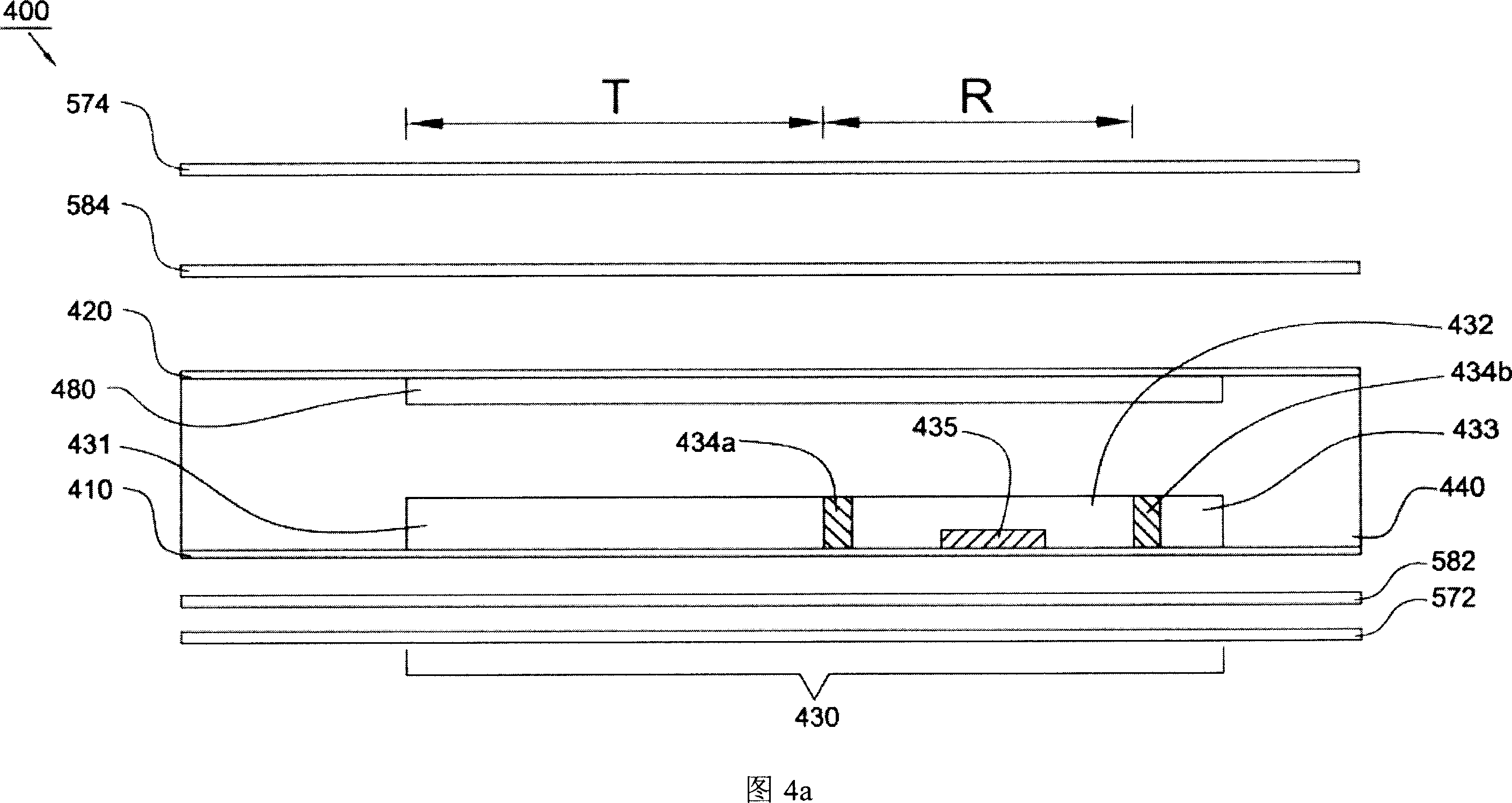
[0044] Please refer to FIG. 4a, a transflective liquid crystal display 400 according to an embodiment of the present invention includes an active element array substrate 410, an opposite substrate 420, and a liquid crystal layer 440 disposed between the two substrates 410, 420. The liquid crystal layer 440 includes For example, positive type liquid crystal molecules or negative type liquid crystal molecules. An upper polarizer 574 is disposed above the opposite substrate 420 , and an upper retardation plate (retardation plate) 584 is disposed between the upper polarizer 574 and the opposite substrate 420 . A lower polarizer 572 is disposed under the active device array substrate 410 , and a lower phase retardation plate 582 is disposed between the active device array substrate 410 and the lower polarizer 572 . Please refer to FIG. 4b, on the active device array substrate 410, there are a plurality of scanning lines 450 and a plurality of data lines 460 facing the opposite subs...


PUM


Abstract

The invention provides a semi-penetrating LCD. By setting a resistor between a penetrating electrode and a reflecting board, or by connecting in a floating and insulated way the reflecting board above the penetrating electrode and a grounding electrode, and adjusting the electric field size in the reflecting zone, the phase delay of the liquid crystal layer in the reflecting zone and the penetrating zone is adjusted, so that the thickness of the penetrating zone is actually same with that of the reflecting zone, this avoids the complicated making process for two layers of gap.

Description

technical field [0001] The invention relates to a liquid crystal display, in particular to a semi-transmissive liquid crystal display. Background technique [0002] Please refer to FIG. 1 , a conventional double-layer liquid crystal cell transflective liquid crystal display 100 includes two polarizers 132 , 134 , and two compensation films 122 , 124 are disposed between the two polarizers 132 , 134 . Two substrates 112, 114 are sandwiched between the two compensation films 122, 124, a liquid crystal layer 140 with a thickness d is provided between the two substrates 112, 114, and a reflector with a plurality of openings is provided on the substrate 114. Plate 150. The light 160 provided by the backlight (not shown in the figure) passes through the substrate 114, the opening of the reflector 150 and the liquid crystal layer 140, and reaches the observer's eyes; the external light 170 passes through the substrate 112 and the liquid crystal layer 140, and passes through the re...

Claims


Application Information

Patent Timeline
IPC IPC(8): G02F1/136G02F1/1335G02F1/133
Inventor 徐芝珊黄炳文陈明武翁浩杰
Owner WINTEK CORP
Why Eureka
Try Eureka