
Lamp with infrared reflection coating

A technology for electric lamps and filaments, which is applied to circuits, incandescent lamps, electrical components, etc., and can solve the problems of returning to the filament to reflect infrared radiation interference, support structure shadows, etc.

Inactive Publication Date: 2008-01-23
FLOWIL INT LIGHTING HLDG BV
View PDF4 Cites 2 Cited by
  • Summary
  • Abstract
  • Description
  • Claims
  • Application Information

AI Technical Summary

Problems solved by technology

[0006] Unfortunately, trying to place a filament for ≥200 volts, ≤200 watts in a luminaire that has a coating to reflect the IR radiation back to the (filament) coil is very difficult because of the required support structure that would cause shadowing, or Can interfere with reflected infrared radiation returning to the filament

Method used


Image

  • Lamp with infrared reflection coating
  • Lamp with infrared reflection coating
  • Lamp with infrared reflection coating

Examples


Embodiment Construction

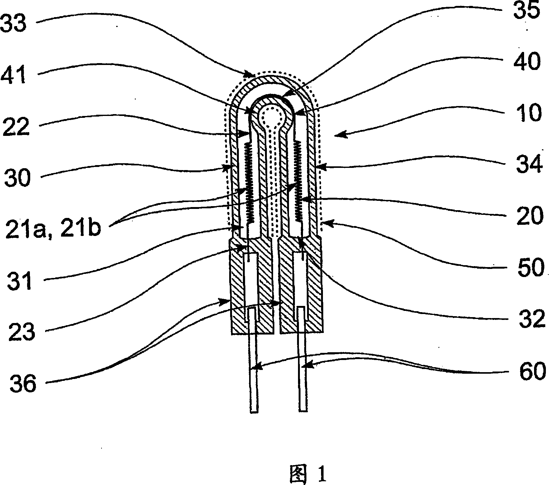
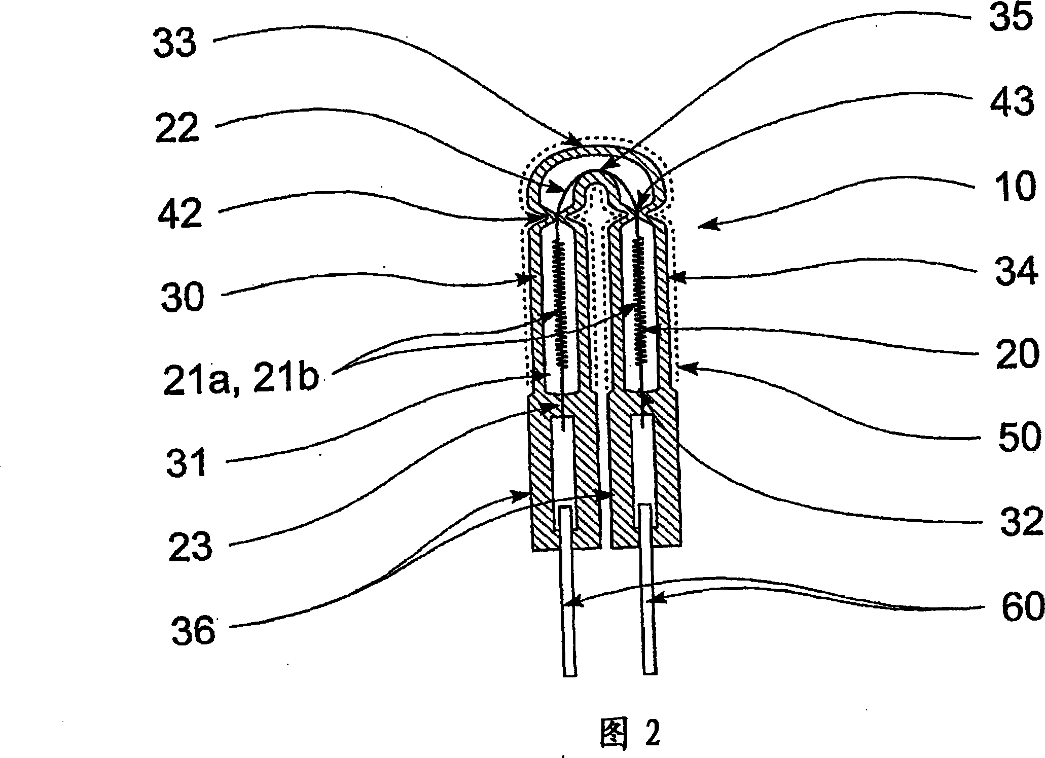
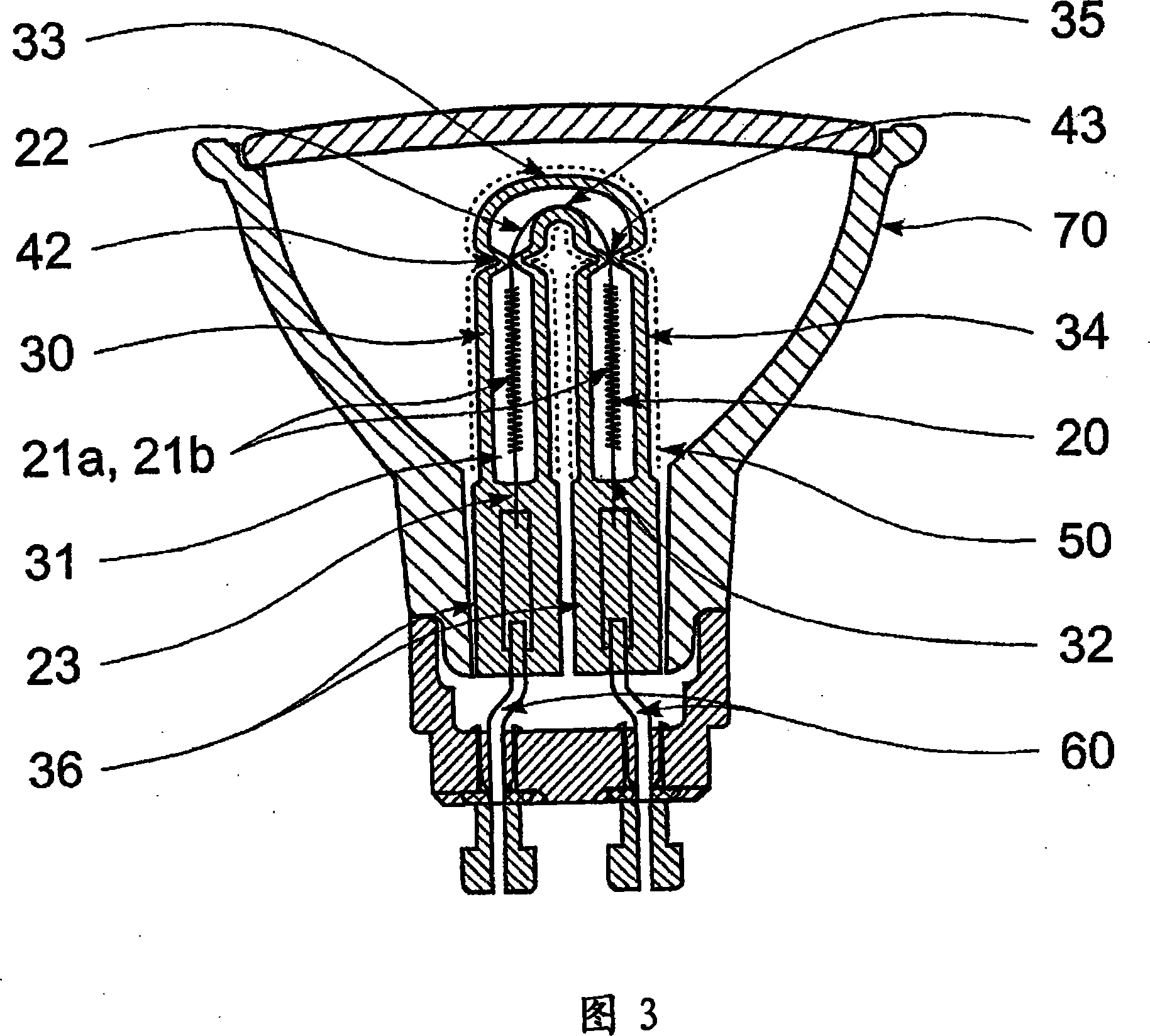
[0022] Figure 1 shows a first embodiment of a luminaire 10 according to the invention. The electric lamp 10 comprises a filament 20 housed within a quartz tube 30 . Inside the quartz tube 30 there is a hollow central region 31 in which the filament 20 is accommodated. As can be seen, the quartz tube 30 has a substantially U-shaped geometry such that the two end regions 34 of the tube are substantially adjacent to each other. Connecting the two end regions 34 together is a U-bend region 33 which is preferably bent such that the two end regions 34 of the quartz tube 30 are very close to each other. It is further desirable that the axes along the center of the quartz tube 30 in each end region 34 be parallel to each other. It can also be seen from the figure that the hollow central region 31 does not extend along the full length of the quartz tube 30 but is actually sealed in a hermetic manner at each end 32 of the quartz tube 30 . This simple design results in an easily manuf...


PUM


Abstract

This invention relates to an electric lamp (10) formed from a quartz tube (30) incorporating a U-bend (33). The filament (20) lies within a hollow central region (31), which is sealed at each end (32) in an airtight manner. Specific positioning means (40) are provided in the lamp (10) for insuring that sections of the filament (20) lie along these central axis of the puartz tube (30).

Description

technical field [0001] The invention relates to an electric lamp, especially an electric lamp with an infrared reflective coating. Background of the invention [0002] Since its invention, the light bulb or light bulb has become a very common household electronic device that people are accustomed to using as a light source. The simple electric light has taken many different forms over the years, from incandescent filaments that produce light and heat to fluorescent and discharge tubes. Of these lamps, however, simple incandescent filament electric lamps have been very common in domestic use. This is mainly due to the fact that such lamps are simple to manufacture, very reliable, do not require any external electrical controls, and are therefore very cheap and readily available to anyone. [0003] However, there are significant efficiency problems in filament-type light bulbs or lamps. In particular, using an extremely hot filament to generate light is not a particularly e...

Claims


Application Information

Patent Timeline
Patent Type & Authority Applications(China)
IPC IPC(8): H01K1/32H01K1/02H01K1/18
CPCH01K5/02H01K3/20H01K1/24H01K1/325H01K1/18
Inventor J·胡克
Owner FLOWIL INT LIGHTING HLDG BV
Learn More