Supercharge Your Innovation With Domain-Expert AI Agents!

Extrusion nozzle for extruding hollow profiled elements

A profile and hollow technology, applied in the field of extrusion nozzles, can solve the problems of reducing strength and high processing cost of extrusion nozzles, and achieve the effect of low manufacturing cost

Inactive Publication Date: 2008-01-30
托普弗塑料技术股份有限公司
View PDF2 Cites 0 Cited by
  • Summary
  • Abstract
  • Description
  • Claims
  • Application Information

AI Technical Summary

Problems solved by technology

The bonding phenomenon also has the disadvantage that the seams reduce the strength, which can be reflected in the technical inspection of the profiles
[0009] This extrusion nozzle is expensive to tool, primarily because of the mandrel support plate

Method used


Image

  • Extrusion nozzle for extruding hollow profiled elements
  • Extrusion nozzle for extruding hollow profiled elements
  • Extrusion nozzle for extruding hollow profiled elements

Examples


Embodiment Construction

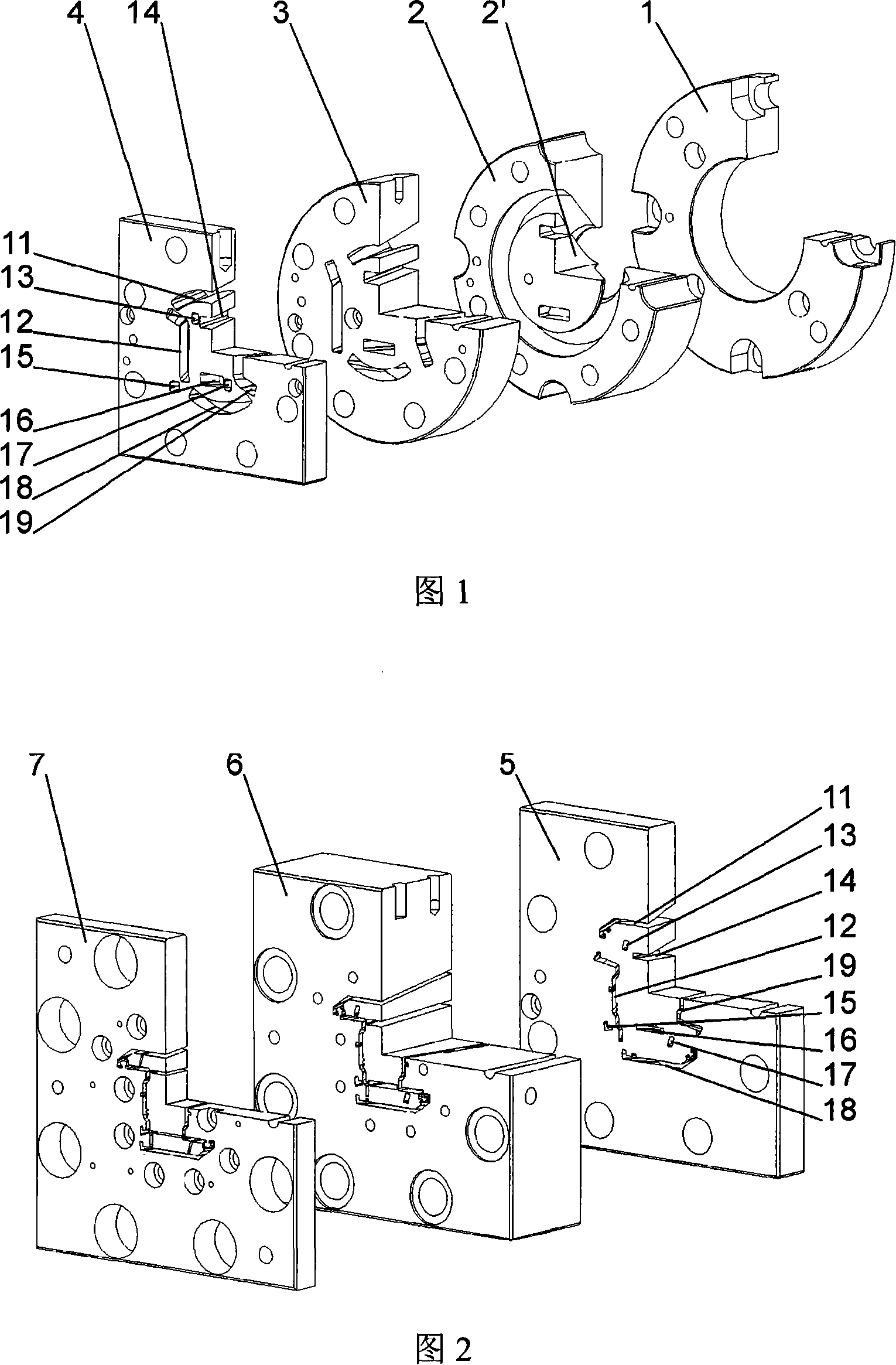
[0028] Starting from a circular melt flow in flange plate 1 ( FIG. 1 ), the melt flow is transformed into a circular shape in distribution plate 2 with spreading tip 2 ′. Here, the melt stream is reshaped into a shape that is larger than the desired size. The residence time of the extrudate is thus extended, which allows the material to be homogenized to a certain extent, which is necessary to increase production efficiency. This circular shape is then subdivided again in the other plates 3 and 4 by segment-shaped flow channels 11 - 19 . These segmented runners 11-19 themselves form separate, independent runners whose shape and position correspond to those of the finally produced profiles.

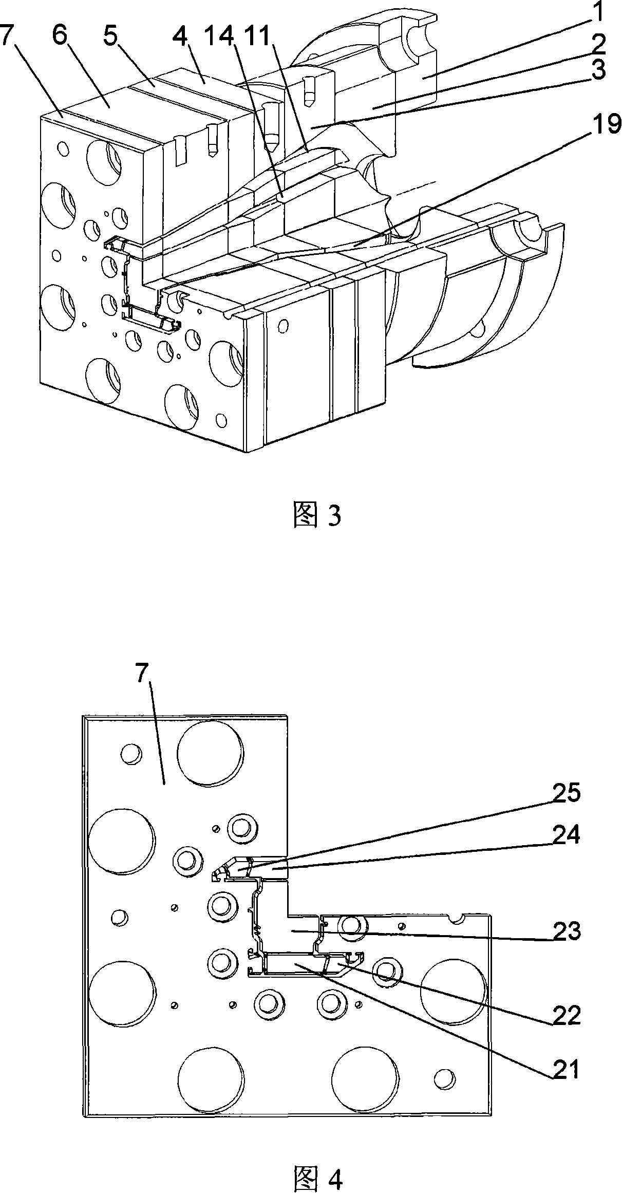
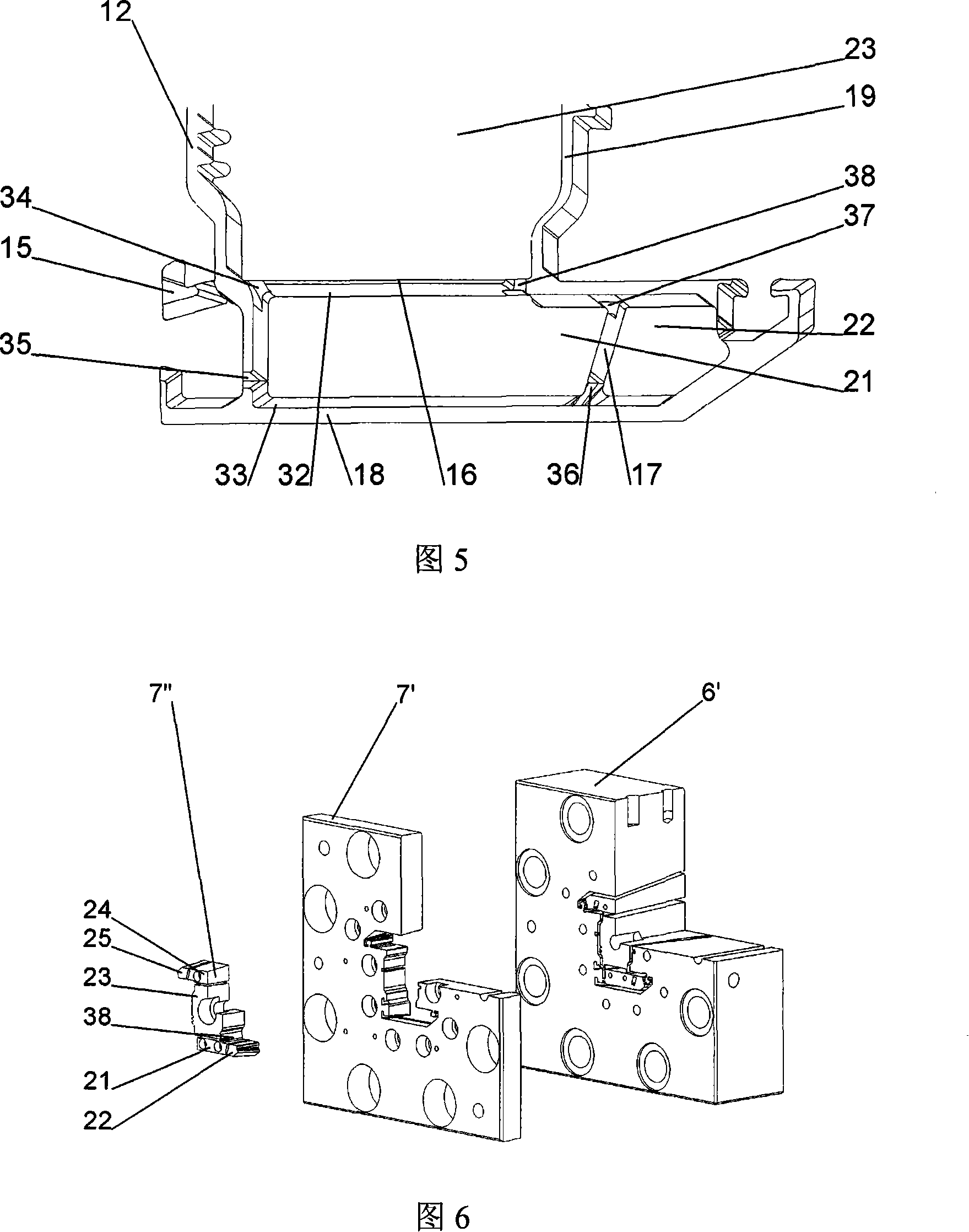
[0029] In subsequent plates 5 , 6 and 7 ( FIG. 2 ), the segment-shaped flow channels 11 - 19 are gradually adjusted in position and thickness to the subsequent profile shape. The core part of the present invention is that these segmented flow channels 11-19 are independent of each other ...


PUM


Abstract

The invention relates to an extrusion nozzle comprising at least one core (21-25). The extrusion nozzle is also equipped with a plurality of flow channels (11-19) for the melt flow which merge into the desired shape within the extrusion nozzle. The extrusion nozzle comprises a plurality of plates (1-7), the flow channels (11-19) of all plates (3-7) having at least one core except the end plate (7) are separated from each other, so that At least one core (21-25) is connected to the remaining plates by connecting elements (34-38) between the runners (11-19). When the flow channels (11-19) in the end plate (7) are connected to each other continuously, at least one core (21-25) of the end plate (7) is screwed to the corresponding core of the adjacent plate (6) . When the runners (11-19) in the end plate (7) are connected to each other only over part of their length, at least one core (21-25) of the end plate (7) is connected to the remaining plate ( 7) Connected.

Description

technical field [0001] The invention relates to an extrusion nozzle for extruding hollow profiles, in particular window profiles, comprising one or more cores, wherein a plurality of flow channels for the melt flow are formed in the extrusion tube Merge inside mouth into desired shape. Background technique [0002] Extrusion can be used for the continuous manufacture of plastic profiles and semi-finished products. The raw materials (mainly thermoplastic polymers) are fed to the extruder in the form of powder or pellets, possibly together with additives such as colorants, fillers, reinforcing fibers, etc. [0003] An extruder consists of several functional zones. The first functional area is the solid feeding area. In this zone, plastics in the form of granules, granules or powder are introduced and advanced. The advance mechanism varies with the design of the extruder. Other functional zones may be, for example, a heating zone in which the raw material is heated and pre...

Claims


Application Information

Patent Timeline
Patent Type & Authority Applications(China)
IPC IPC(8): B29C47/20B29C47/08B29C48/11B29C48/12B29C48/30B29C48/32
CPCB29L2031/60B29C47/12B29C47/0028B29C47/0822B29C48/11B29C48/2562B29C48/12
Inventor S·托普
Owner 托普弗塑料技术股份有限公司
Features
  • R&D
  • Intellectual Property
  • Life Sciences
  • Materials
  • Tech Scout
  • Unparalleled Data Quality
  • Higher Quality Content
  • 60% Fewer Hallucinations
Learn More