Method of manufacturing metal film pattern forming body

A pattern forming and metal film technology, applied in conductive pattern formation, photolithography/pattern, pattern and photolithography, etc., can solve the problems of antenna plating pattern shape change and increase cost

Inactive Publication Date: 2008-03-19
SAMSUNG ELECTRO MECHANICS CO LTD
View PDF0 Cites 8 Cited by
  • Summary
  • Abstract
  • Description
  • Claims
  • Application Information

AI Technical Summary

Problems solved by technology

This causes a change in the shape of the antenna plating pattern
[0011] Therefore, this double injection molding requires a mold with high precision compression molding / pressing, thus increasing the cost

Method used


Image

  • Method of manufacturing metal film pattern forming body
  • Method of manufacturing metal film pattern forming body
  • Method of manufacturing metal film pattern forming body

Examples


Embodiment Construction

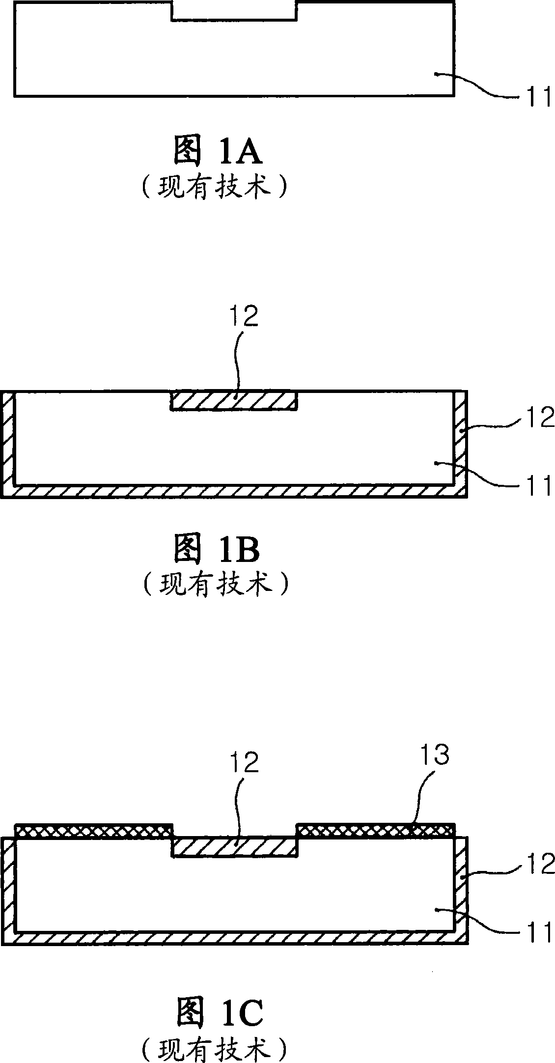
[0026] Exemplary embodiments of the present invention will be described in detail below with reference to the accompanying drawings.

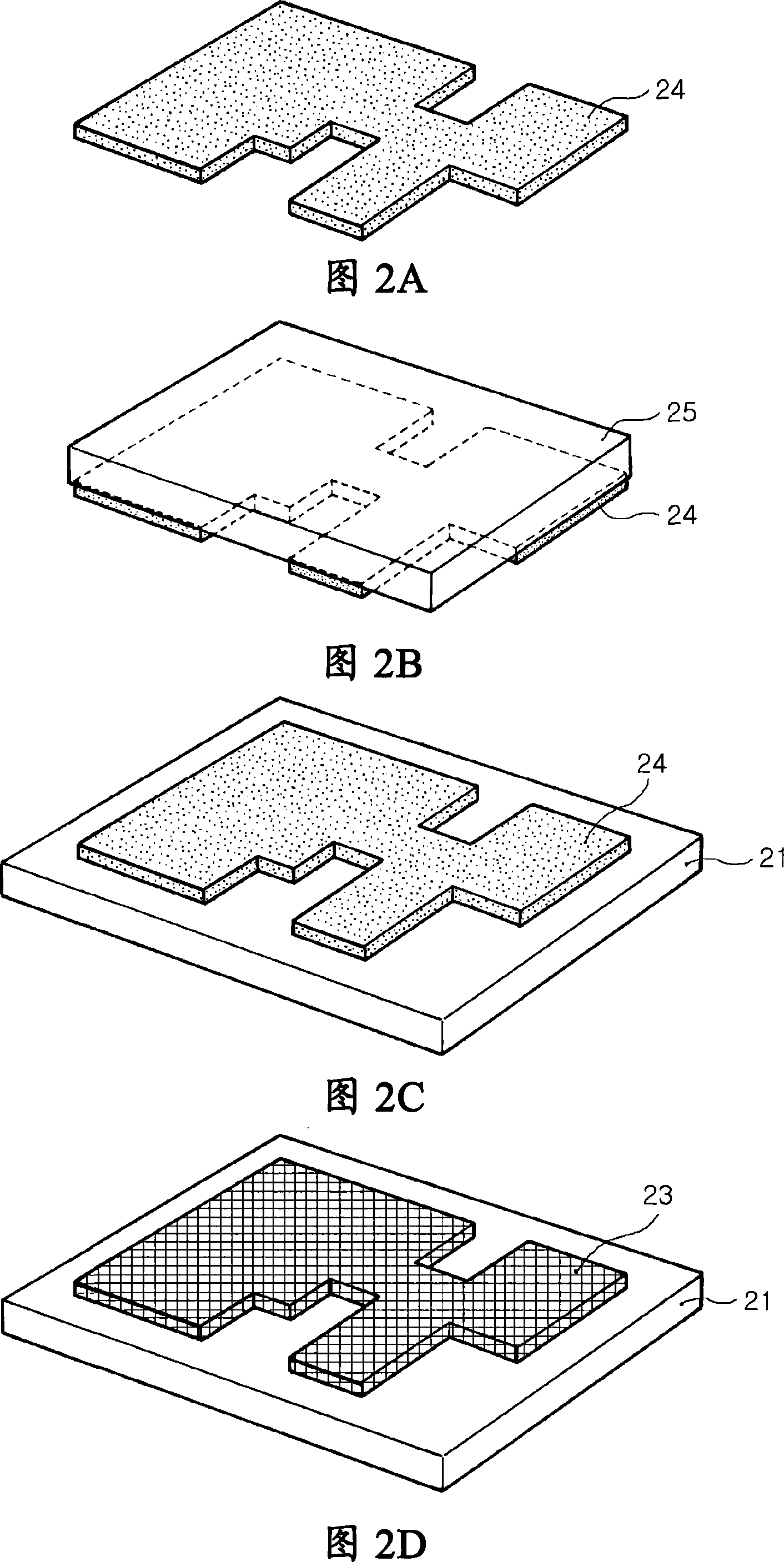
[0027] 2A to 2D illustrate a method of manufacturing a metal film pattern molded body having a plated conductive film formed on a plastic base according to an exemplary embodiment of the present invention.

[0028] Referring to FIG. 2A, a catalyst is used to form a desired antenna pattern.

[0029] The catalyst 24 reacts chemically with the plastic substrate on the surface of the plastic substrate to activate the surface of the plastic substrate, so that the surface of the plastic substrate can be directly coated with metal. Therefore, the catalyst 24 in this embodiment may contain components that chemically modify the plastic substrate and components that absorb the plating solution.

[0030] The ingredients that modify the plastic matrix can vary with the type of modification. Specifically, in the case where the chemical modification is hyd...


PUM


Abstract

A method of manufacturing a metal film pattern forming body, the method including: forming a desired metal film pattern on one surface of a stamp by using a catalyst for activating a surface of a plastic base; activating the surface of the plastic base by transferring the catalyst formed on the surface of the stamp onto the surface of the plastic base; and plating the surface of the activated plastic base.

Description

[0001] Related Application Cross Reference [0002] This application claims priority from Korean Patent Application No. 2006-89426 filed with the Korean Intellectual Property Office on September 15, 2006, the disclosure of which is incorporated herein by reference. technical field [0003] The present invention relates to a method of forming a metal film, and more particularly, to a method of forming a metal film by plating the surface of a plastic base. Background technique [0004] Recently, as the size of mobile communication terminals continues to decrease, the terminals have tended to use built-in antennas instead of conventional external antennas. Furthermore, various functions added to the terminal basically require the improvement of the built-in antenna to be able to respond to the new frequency band. [0005] In a conventional built-in antenna, a metal plate is attached to a plastic base, and the radiator of the antenna is embodied by adjusting the pattern shape o...

Claims


Application Information

Patent Timeline
Patent Type & Authority Applications(China)
IPC IPC(8): H01Q1/00H05K3/00H05K3/10
CPCH05K3/1275C23C18/38H05K2203/0534H05K3/182C23C18/1608H05K2203/0338C23C18/30H05K2203/0709
Inventor 成宰硕罗基龙崔益彰
Owner SAMSUNG ELECTRO MECHANICS CO LTD
Why Eureka
Try Eureka