
Fixer, image forming apparatus, and image forming method

A technology for fixing parts and driving devices, which is applied in the field of image forming devices and copiers, can solve problems such as cam shape constraints, and achieve the effects of optimal pressure and good fixing performance

Inactive Publication Date: 2008-05-14
RICOH KK
View PDF3 Cites 8 Cited by
  • Summary
  • Abstract
  • Description
  • Claims
  • Application Information

AI Technical Summary

Problems solved by technology

[0014] However, in this case, it is necessary to ensure the installation space of the optical sensor or micro switch, or to install parts related to the optical sensor or micro switch, such as wiring, light shielding plate, etc., and the shape of the cam is restricted.

Method used


Image

  • Fixer, image forming apparatus, and image forming method
  • Fixer, image forming apparatus, and image forming method
  • Fixer, image forming apparatus, and image forming method

Examples


Embodiment Construction

[0060] Hereinafter, the best mode for carrying out the present invention will be described in detail with reference to the accompanying drawings. In each figure, the same or corresponding parts are marked with the same symbols, and repeated explanations are appropriately omitted.

[0061] In the following embodiments, various limitations are made on constituent elements, types, combinations, shapes, relative arrangements, etc., but these are merely examples, and the present invention is not limited thereto.

[0062] Embodiment 1

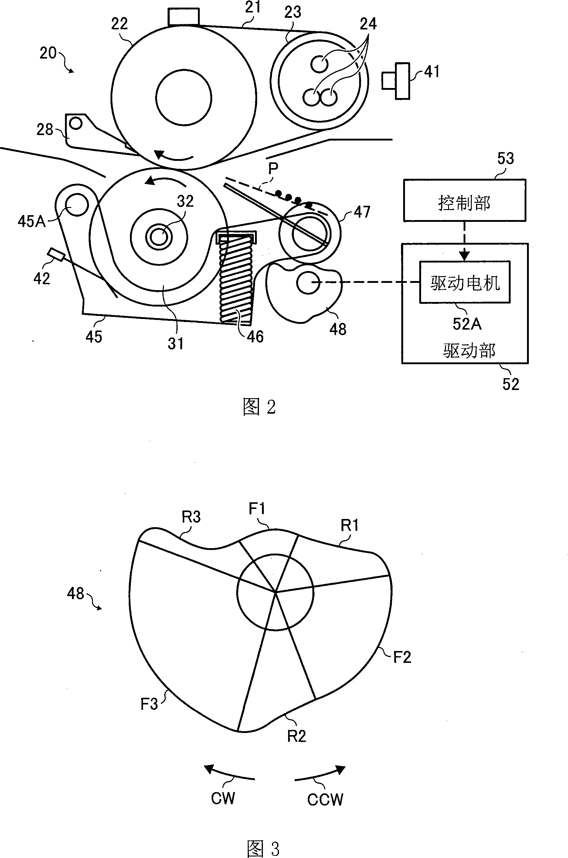
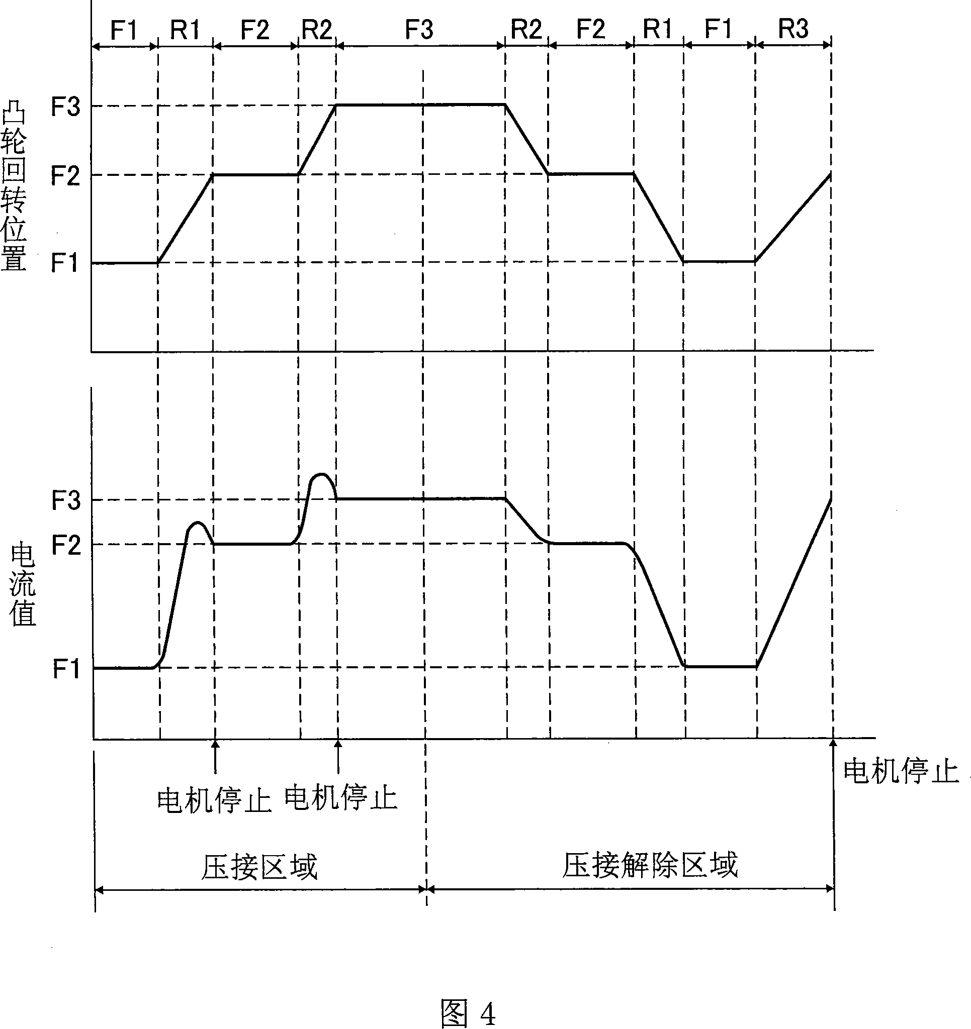
[0063] Embodiment 1 of the present invention will be described in detail with reference to FIGS. 1-4.

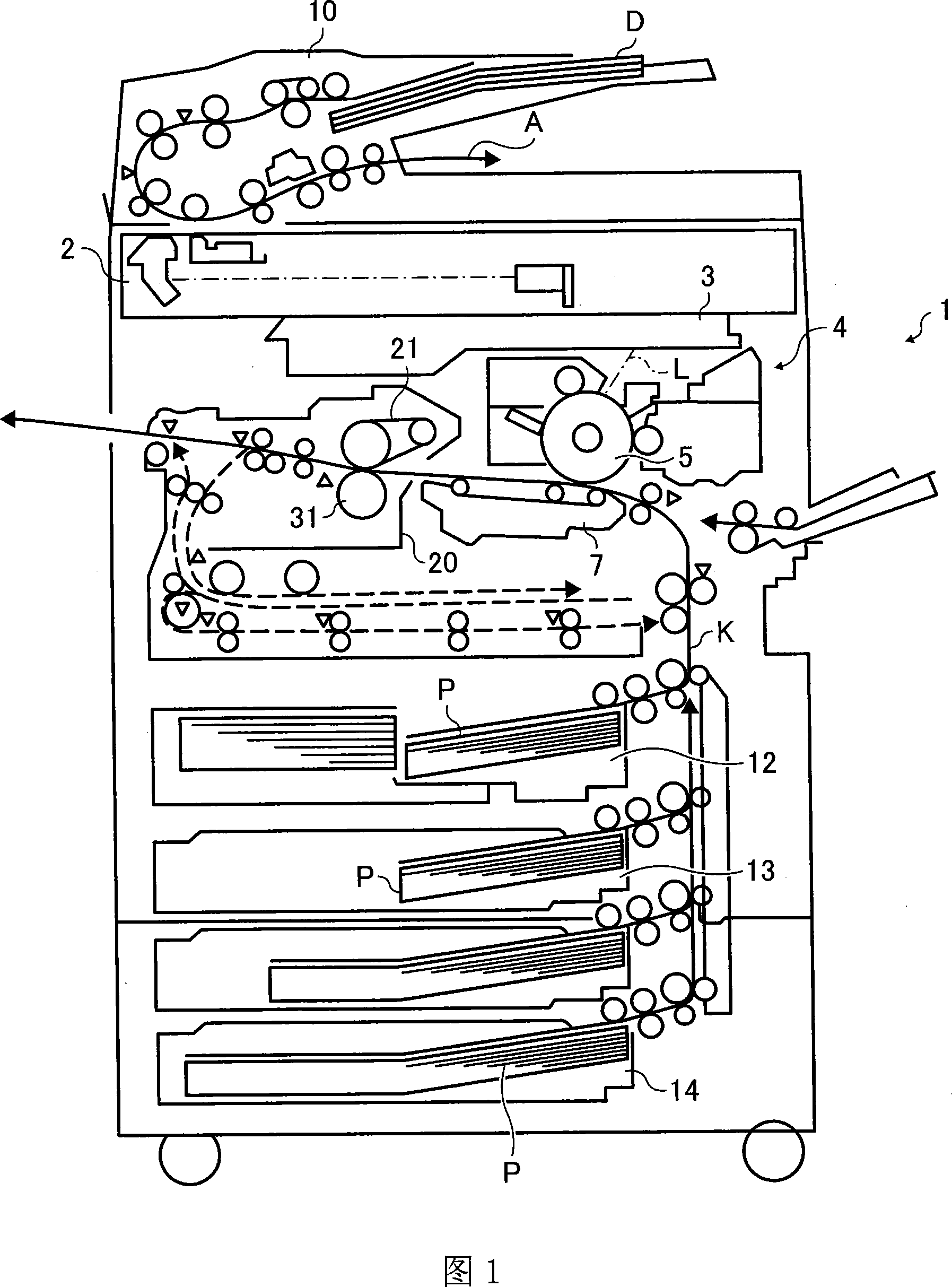
[0064] First, referring to FIG. 1 , the overall configuration and operation of the image forming apparatus will be described.

[0065] In FIG. 1, reference numeral 1 denotes an apparatus main body of a copying machine as an image forming apparatus, reference numeral 2 denotes a document reading section for optically reading image information of a...


PUM


Abstract

The present invention relates to a fixing device and an image forming device. The fixing device includes: a fixing part (21), which heats and melts the toner image; a pressing part (31), which is in pressure contact with the fixing part to form a clamping part; a control unit, which controls the pressure of the pressing part on the The relative pressing force of the fixing unit. The control unit includes: a cam (48), which changes the rotary position of the cam, so that the relative pressing force of the pressing member to the fixing member is variable; a driving device (52), which drives the cam to rotate; a control part, When the cam is driven to rotate, the change of the current value flowing through the driving device is detected to control the rotation position of the cam. When the cam is rotated so that the relative pressing force of the pressing member to the fixing member is variable, the current value of the driving motor for driving the cam is detected to accurately and easily grasp the variable pressing force, so that the clamping The pressing force of the holding part is optimized, and a good fixing property can be stably ensured.

Description

technical field [0001] The present invention relates to an image forming apparatus such as a copying machine, a printer, a facsimile machine, and a compound machine, and a fixing device provided therein, and more particularly, to a fixing device and an image forming apparatus in which the pressing force of a pressing member pressing the fixing member is variable. Background technique [0002] Conventionally, in image forming apparatuses such as copiers and printers, a fixing member such as a fixing roller, a fixing belt, and a fixing sleeve are brought into contact with a pressing member such as a pressure roller or a pressure belt to form a nip, and the recording medium is conveyed to this area. The nip unit fixes the toner image on the recording medium, and such a fixing device is widely used. [0003] Also, in such a fixing device, a technique of varying the pressing force of a pressing member that presses the fixing member is widely used, for example, refer to Patent Doc...

Claims


Application Information

Patent Timeline
Patent Type & Authority Applications(China)
IPC IPC(8): G03G15/20G03G15/00G03G13/20
Inventor 御沓泰成
Owner RICOH KK
Learn More