
Fixer image apparatus, and image forming apparatus

A technology for fixing components and driving devices, which is applied in the fields of copiers and image forming devices, can solve problems such as cam shape constraints, and achieve the effects of optimal pressure and good fixing performance

Inactive Publication Date: 2010-11-17
RICOH KK
View PDF10 Cites 0 Cited by
  • Summary
  • Abstract
  • Description
  • Claims
  • Application Information

AI Technical Summary

Problems solved by technology

[0014] However, in this case, it is necessary to ensure the installation space of the optical sensor or micro switch, or to install parts related to the optical sensor or micro switch, such as wiring, light shielding plate, etc., and the shape of the cam is restricted.

Method used


Image

  • Fixer image apparatus, and image forming apparatus
  • Fixer image apparatus, and image forming apparatus
  • Fixer image apparatus, and image forming apparatus

Examples


Embodiment Construction

[0060] Hereinafter, the best mode for carrying out the present invention will be described in detail with reference to the drawings. In each figure, the same or corresponding parts are marked with the same symbols, and repeated descriptions are appropriately omitted.

[0061] In the following embodiments, although various restrictions are made on constituent elements, types, combinations, shapes, relative arrangements, etc., these are merely examples, and the present invention is not limited thereto.

[0062] Embodiment 1

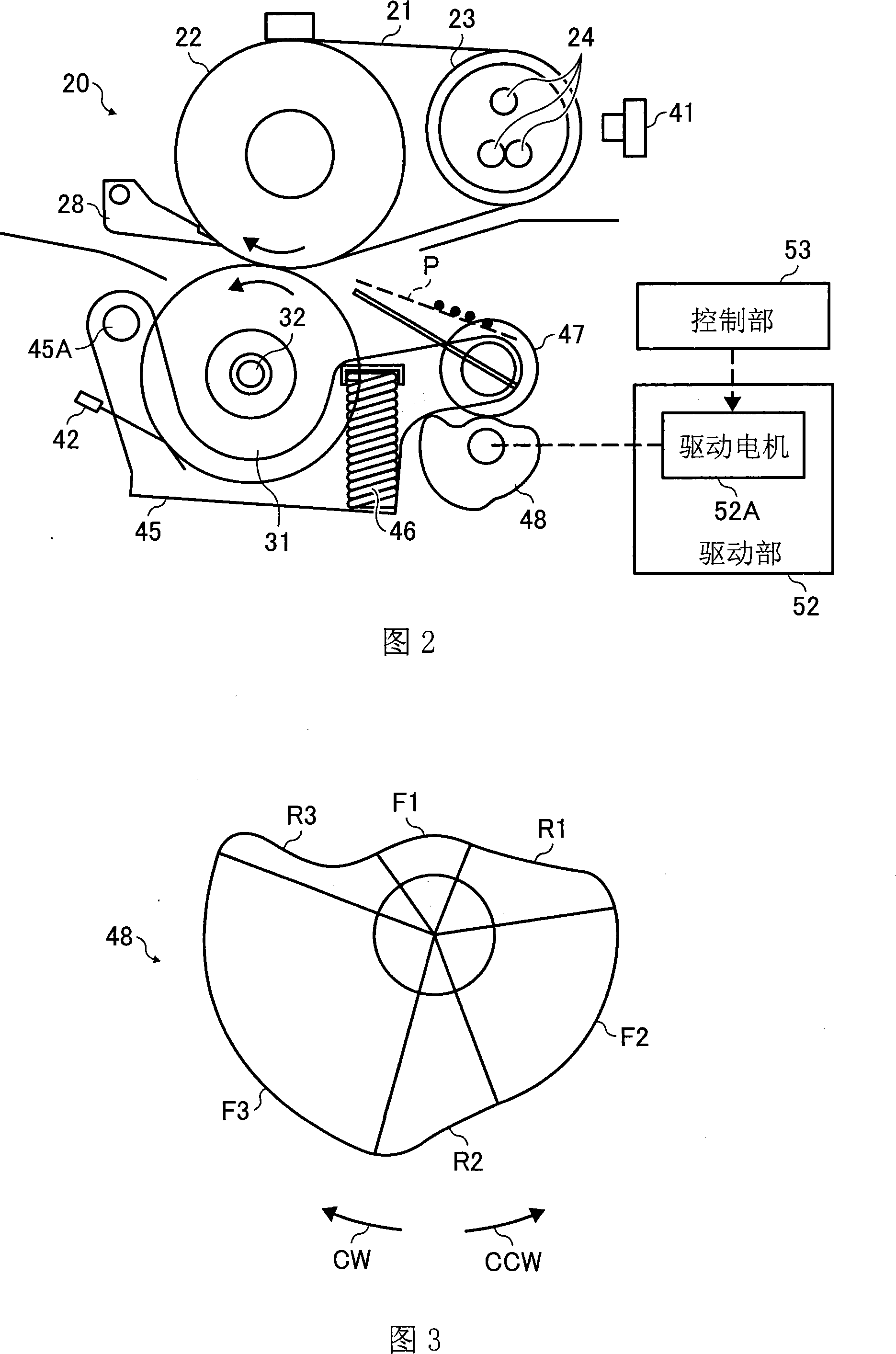
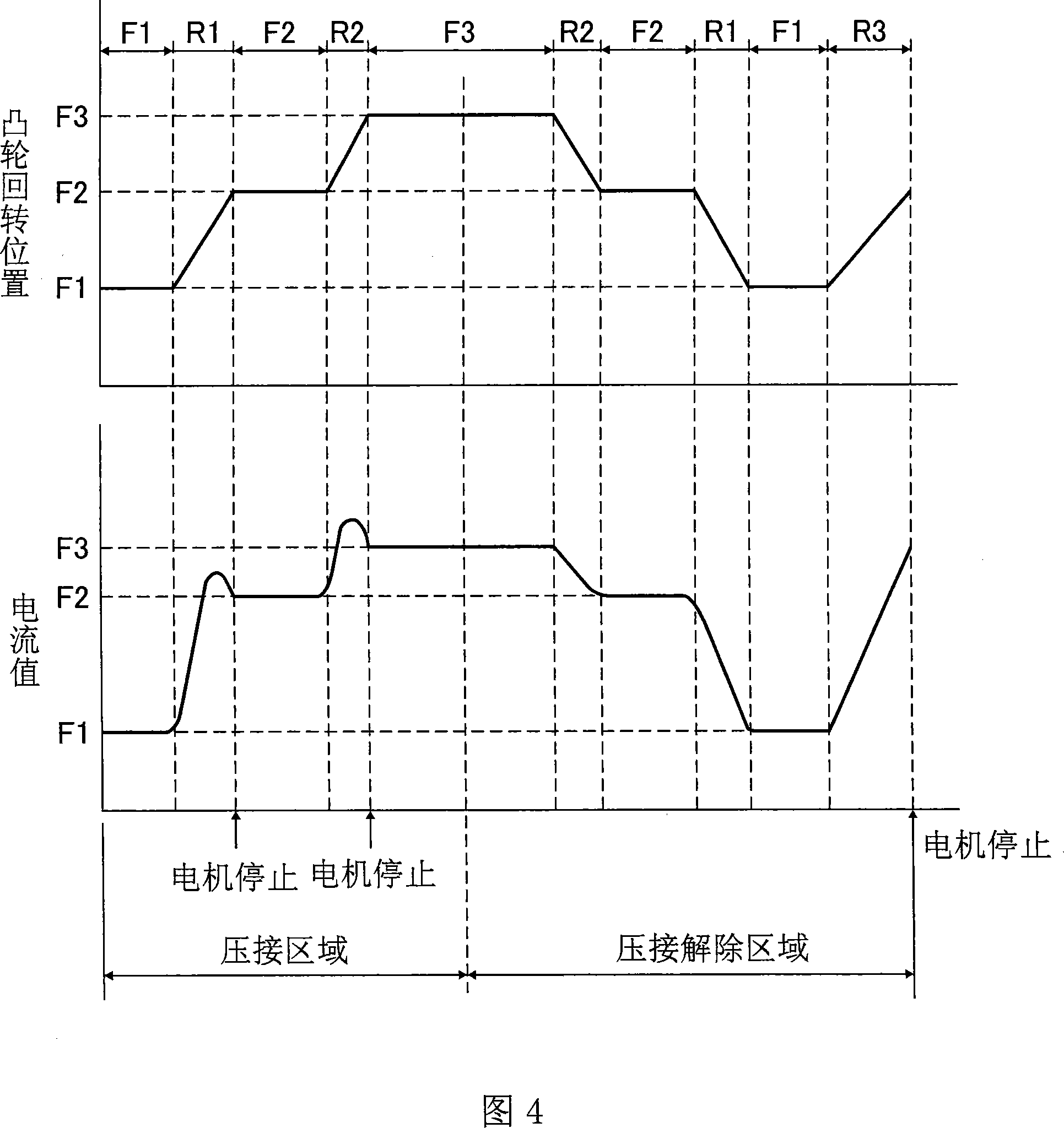
[0063] Reference Figure 1-Figure 4 The first embodiment of the present invention will be described in detail.

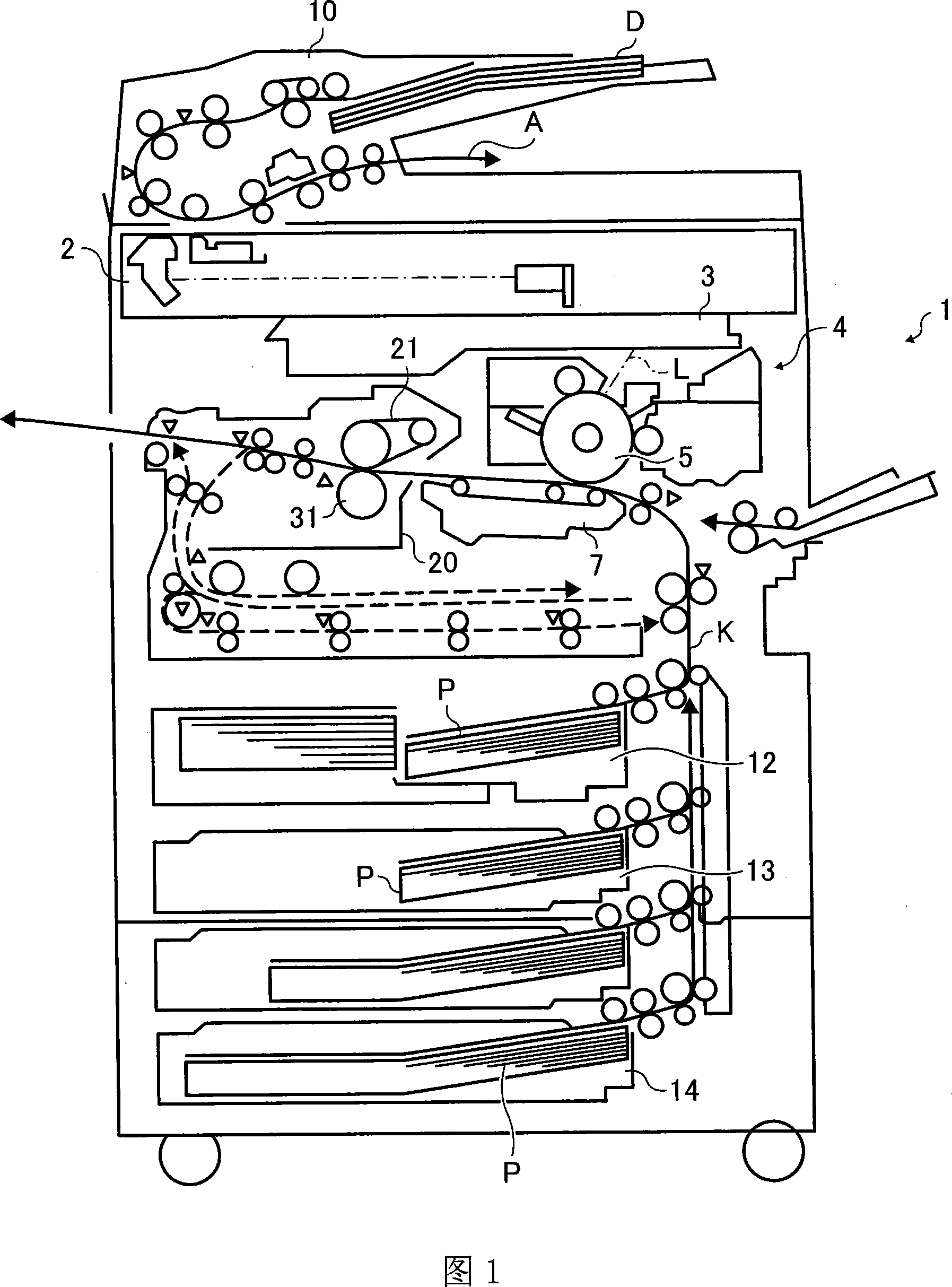
[0064] Reference first figure 1 The overall configuration and operation of the image forming apparatus will be described.

[0065] in figure 1 Here, the symbol 1 indicates the main body of the copier as an image forming apparatus, the symbol 2 indicates a document reading section for optically reading the image information of the manuscript D, and the sym...


PUM


Abstract

The invention relates to a fixer and an image forming device. The fixer includes a fixing member configured to fuse a toner image with heat, a pressure member configured to press against the fixing member to form a nip therebetween, and a control unit configured to control a relative pressure of the pressure member against the fixing member. The control unit includes a cam configured to change a rotation position thereof to change the relative pressure of the pressure member against the fixing member, a driving source configured to drive the cam to rotate, and a controller configured to detect a rotation position of the cam by detecting changes in an electrical current that flows in the driving source when the cam is rotated, and control the rotation position of the cam. So that the pressure member can supply the optimized pressure to the fixer, the fixing performance can be ensured.

Description

Technical field [0001] The present invention relates to image forming apparatuses such as copiers, printers, facsimile machines, multifunction machines, and fixing devices provided therein, and more particularly to a fixing device and an image forming apparatus in which the pressing force of a pressing member that presses the fixing member is variable. Background technique [0002] Conventionally, in image forming apparatuses such as copiers and printers, fixing members such as fixing rollers, fixing belts, and fixing sleeves are brought into contact with pressure members such as pressure rollers and pressure belts to form a nip, and the recording medium is transported there. The nip part fixes the toner image on the recording medium, and such a fixing device is widely used. [0003] In addition, in such a fixing device, a technique of changing the pressure of a pressing member that presses the fixing member is widely used, for example, refer to Patent Documents 1-3. [0004] Specif...

Claims


Application Information

Patent Timeline
Patent Type & Authority Patents(China)
IPC IPC(8): G03G15/20G03G15/00G03G13/20
Inventor 御沓泰成
Owner RICOH KK
Learn More