Droplet deposition apparatus

A deposition equipment, droplet technology, applied in printing and other directions, can solve problems such as increasing nozzle spacing

Inactive Publication Date: 2008-07-09
XAAR TECH LTD
View PDF1 Cites 10 Cited by
  • Summary
  • Abstract
  • Description
  • Claims
  • Application Information

AI Technical Summary

Problems solved by technology

The complication of such shared-wall structures is that actuation of selected channels by wall displacement can cause pressure changes in adjacent channels as well, so

Method used


Image

  • Droplet deposition apparatus
  • Droplet deposition apparatus
  • Droplet deposition apparatus

Examples


no. 1 approach

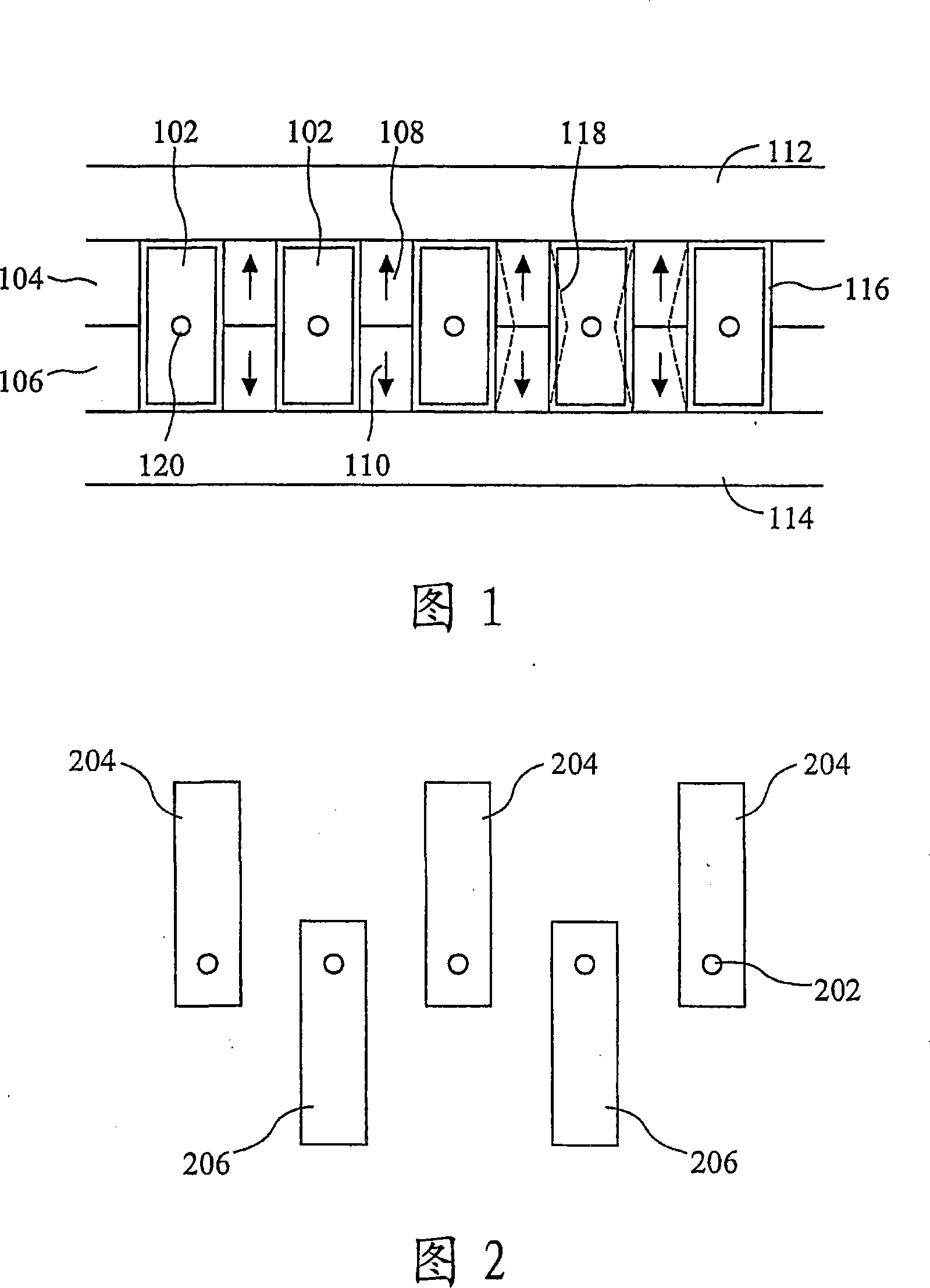
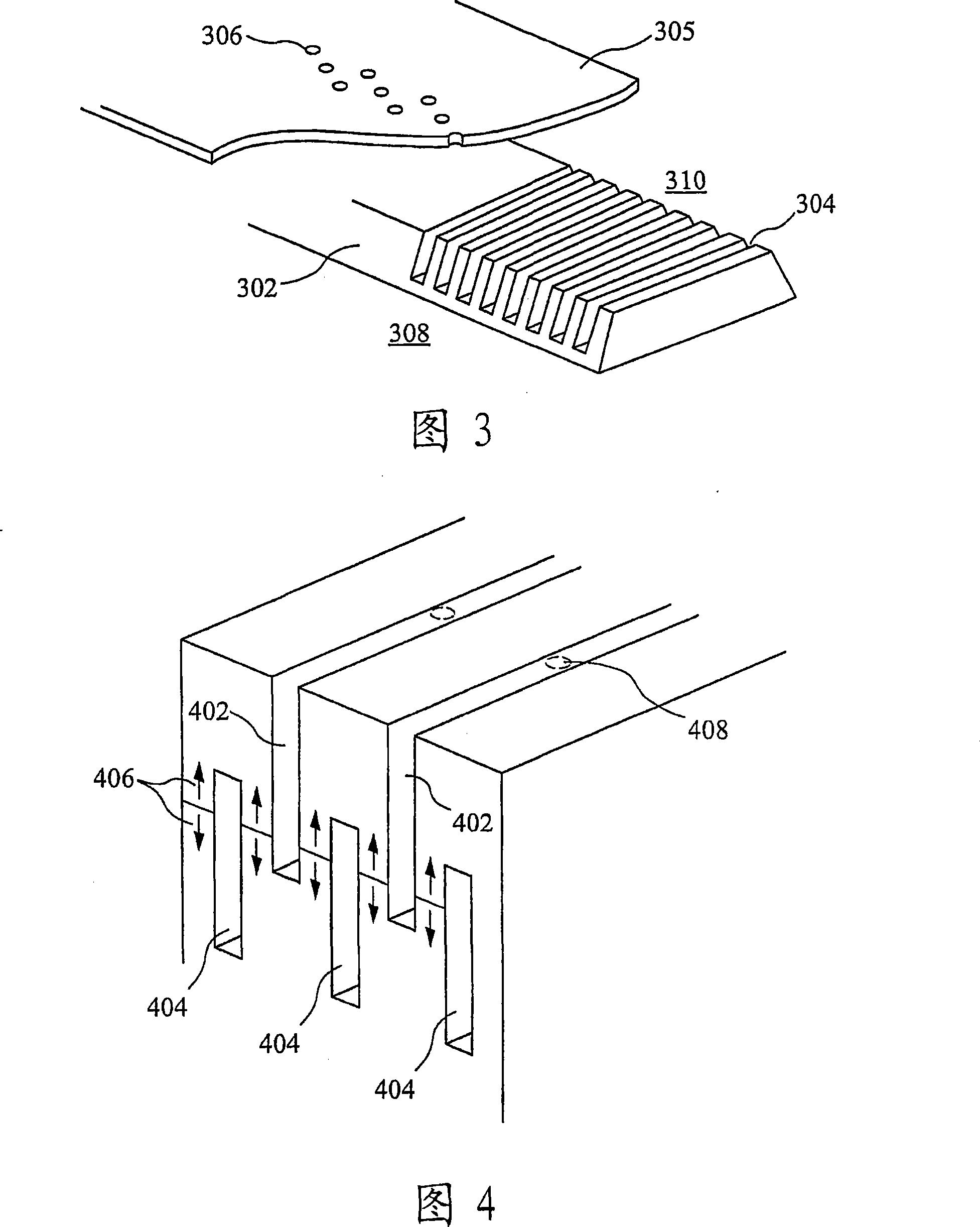
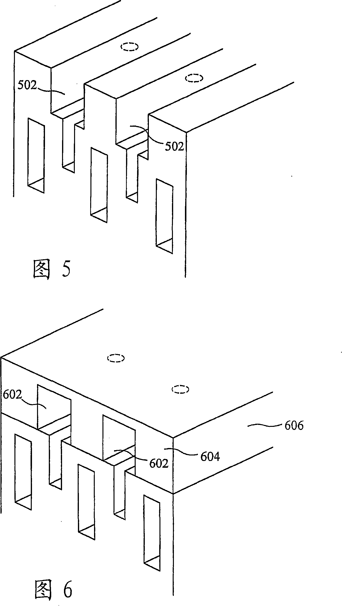
[0034] Referring to Figure 4, there is schematically shown a first embodiment of the invention comprising a body of piezoelectric material (PZT in this example) having an array of channels. The staggered channels are vertically offset, channel 402 is formed in the top surface of the PZT and is open, while channel 404 is formed in the lower part of the PZT and is closed. When the two sets of channels are stacked, the actuation sidewalls are defined by PZT polarized in opposite directions as indicated by arrow 406 in these regions. These sidewalls are formed with electrodes and move laterally in shear mode under the action of an electric field as described above. It can be seen that by actuating the side walls, a pressure change can be created in the channel, resulting in spray from nozzles (shown as dashed line 408) disposed in a nozzle plate (not shown) that is bonded to the upper surface of the PZT and closes the upper channel. droplet.

[0035] The lower channel 404 is not...


PUM


Abstract

An inkjet printhead has a first array of actuable side walls (1507) defining channels (1508) , the actuable sidewalls being displaceable to cause a pressure change in selected channels, alternate channels in the array being firing channels; and a second array of parallel side walls (1503) offset in a channel height direction to define channel extension regions (1504) opening to a respective firing channel (1508) . A nozzle (1506) communicates with each channel extension region. The spacing between adjacent side walls in the second array is large to reduce impedance and the spacing between adjacent actuable side walls in the first array is small to provide for efficient actuation.

Description

technical field [0001] The present invention relates to droplet deposition apparatus and, in an important embodiment, to inkjet printheads, especially drop-on-demand inkjet printheads. Background technique [0002] In known constructions, such as described in EP-B-0 278 590, channels are formed in a body of piezoelectric material and ink droplets are ejected by the action of acoustic waves generated in the ink channel by displacement of the channel walls. Such a wall actuated structure advantageously allows tight channel spacing, and thus narrow nozzle spacing. A complication of such a shared wall structure is that actuation of a selected channel by wall displacement can cause a pressure change also in an adjacent channel, so-called "crosstalk". It has been proposed to address this complexity by using only every other channel for droplet ejection, but this results in increased nozzle spacing. [0003] In EP-B-0 278 590 it is proposed to extend the staggered channels in the...

Claims


Application Information

Patent Timeline
IPC IPC(8): B41J2/14
CPCB41J2/14209B41J2/14B41J2/145B41J2/135
Inventor 保罗·雷蒙德·特鲁里
Owner XAAR TECH LTD
Why Eureka
Try Eureka