Jet fabric dyeing machine

A technology for dyeing machines and fabrics, applied in the direction of liquid/gas/steam jet propulsion fabrics, textile processing machine accessories, liquid/gas/steam fabric treatment, etc., which can solve the problems of different and increased wrinkles

Inactive Publication Date: 2008-09-24
FALMER INVESTMENTS LTD
View PDF2 Cites 11 Cited by
  • Summary
  • Abstract
  • Description
  • Claims
  • Application Information

AI Technical Summary

Problems solved by technology

However, elongated machines have large spans such that the temperature at one end of the machine can be significantly different from the temperature at the other end
Also, the large fabric length can make

Method used


Image

  • Jet fabric dyeing machine
  • Jet fabric dyeing machine
  • Jet fabric dyeing machine

Examples


Embodiment Construction

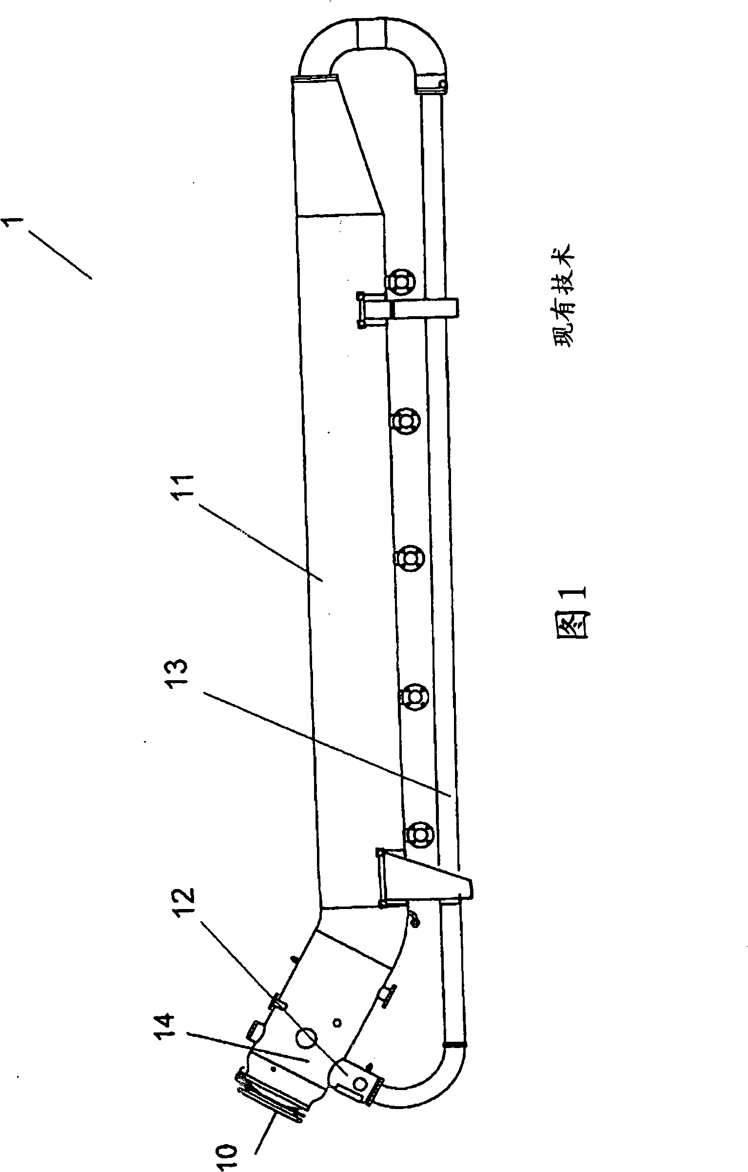
[0028] Figure 1 shows an external side view of a conventional high-speed jet-type fabric dyeing machine through which a circular fabric rope is circulated through which jets of dye liquor are directed onto the fabric by means of nozzles. The fabric and then the discharged dye liquor is fed back to the nozzle.

[0029] The dyeing machine 1 comprises a cloth trough 11 in the form of a horizontally arranged large-diameter pipe or cylindrical container. One end of the cloth chute is inclined upwards and has an outlet therein which is connected to the inlet of a tubular nozzle 12 . The nozzle 12 is also cylindrical, has a smaller diameter than the cloth groove 11, and points in a substantially downward direction. The fabric can pass through a nozzle 12 provided with a nozzle gap or head through which one or more high velocity jets of dye liquor are directed downwards and inwards onto the fabric in the nozzle, thereby in a forward cycle Propel the fabric through the nozzle in the ...


PUM


Abstract

A fabric dyeing machine comprises a travelling tube, a storage chamber in communication with both ends of the travelling tube to form an endless travel path for an endless fabric rope, a nozzle operable to propel an endless fabric rope around the travel path by directing jets of dye liquor onto the endless fabric rope; and an outer vessel enclosing both the storage chamber and the travelling tube. The outer vessel may define the storage chamber, with the travelling tube located inside the outer vessel. The travelling tube and/or the storage chamber may be elongate and arranged along a slope at a few degrees to the horizontal, for example 3 to 5 degrees. A second travelling tube and nozzle can share the storage chamber to give a second endless travel path for the second endless fabric rope.

Description

technical field [0001] The present invention relates to a jet fabric dyeing machine and improvements to the same. Background technique [0002] Jet fabric dyeing machines are used for the wet treatment (dyeing) of fabrics and textile materials arranged in the form of a continuous rope which circulates around the machine in order to come into contact with the dye liquor which is sprayed through jet nozzles which The dye liquor is directed onto the fabric at high speed and propelled in the direction of travel. [0003] Traditionally, these machines comprise: a nozzle through which the fabric is propelled; a traveling tube connected to the outlet of the nozzle along which the fabric travels and in which the fabric soaking in the dye liquor; a cloth trough through which the fabric is passed from the conducting tube into the cloth trough in which the fabric accumulates as excess dye liquor is drained; and a roller which passes the fabric through the cloth trough The tank is sen...

Claims


Application Information

Patent Timeline
IPC IPC(8): D06B3/28D06B3/24D06B23/00D06B23/14
CPCD06B3/28D06B23/042D06B3/20
Inventor 徐达明
Owner FALMER INVESTMENTS LTD
Why Eureka
Try Eureka