Self-starting, permanent-magnet synchronous

A technology of synchronous motors and electric motors, applied in the field of electric motors, can solve problems such as high production costs, and achieve the effects of simple manufacturing, protection from corrosion, and high synchronous torque

Inactive Publication Date: 2008-10-22
WILO SE
View PDF2 Cites 4 Cited by
  • Summary
  • Abstract
  • Description
  • Claims
  • Application Information

AI Technical Summary

Problems solved by technology

This in turn entails considerable manufacturing outlay, which leads to high production costs and makes this type of rotor unsuitable for small power pumps

Method used


Image

  • Self-starting, permanent-magnet synchronous
  • Self-starting, permanent-magnet synchronous

Examples


Embodiment Construction

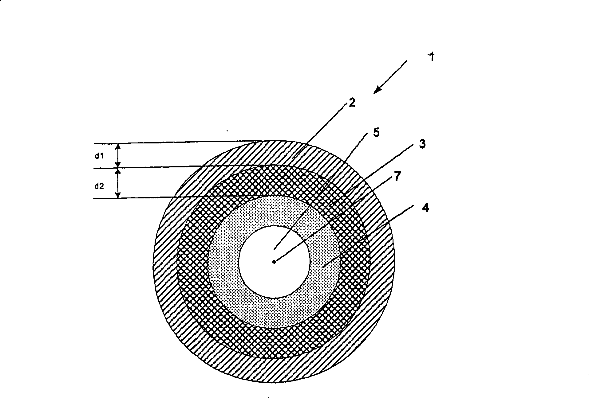
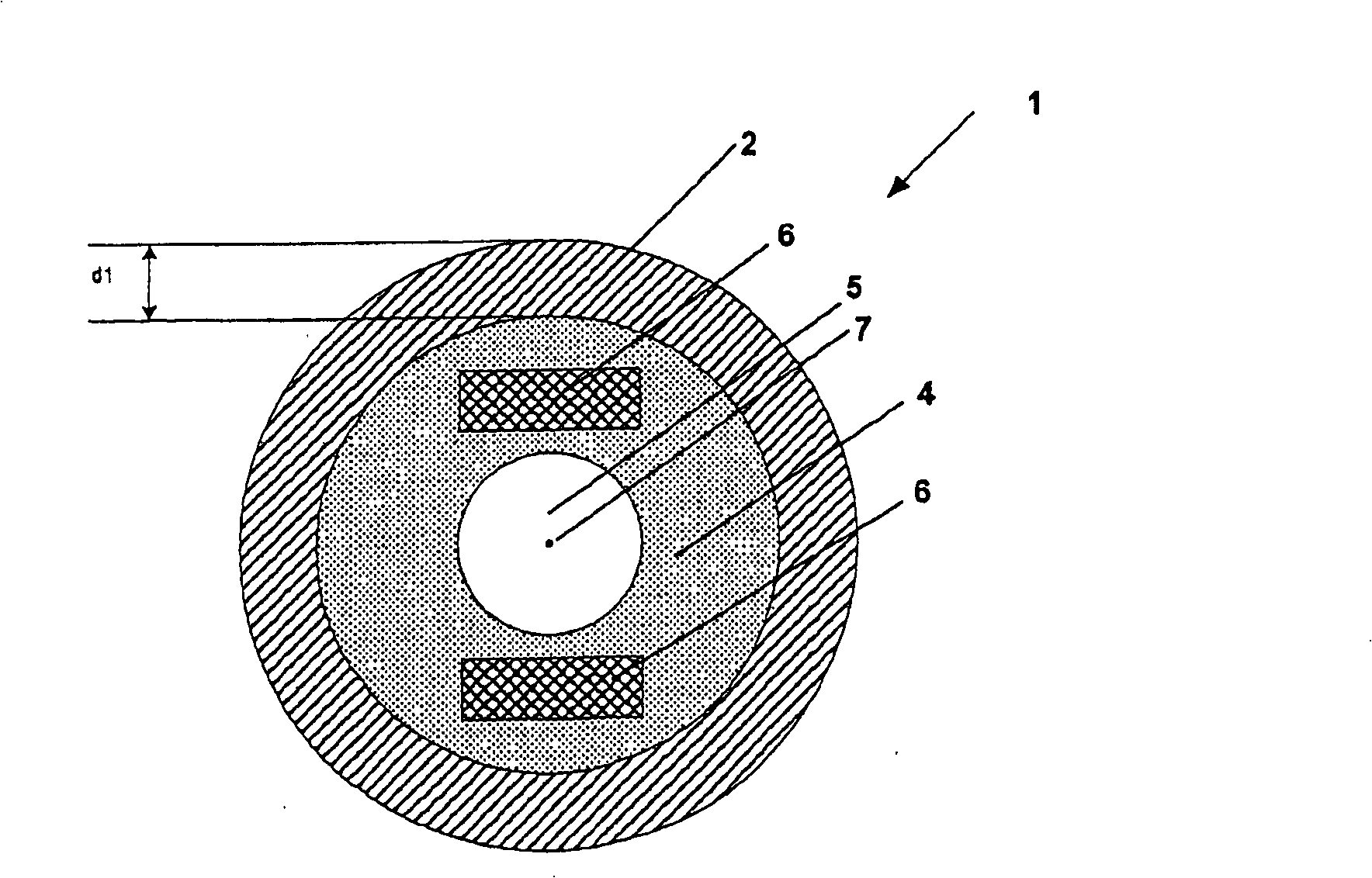
[0032] figure 1 A cross-sectional view of a rotor 1 according to the invention is shown. The rotor 1 has a rotor shaft 5 and an electrically conductive cage winding 2 arranged coaxially to the rotor axis 7 and designed as a solid hollow cylinder. Furthermore, the rotor 1 has a permanent magnet 3 which is likewise designed in the form of a solid hollow cylinder and extends coaxially along at least part of the cage winding 2 . The hollow cylindrical permanent magnet has a thickness d2.

[0033] The permanent magnet 3 is located inside the cage winding 2 and bears against the inner side of the cage winding 2 . The cage winding 2 has a thickness d1 which is preferably between 5% and 30%, in particular between 10% and 20%, of the total radius of the rotor 1 . In contrast, the permanent magnets 3 have an axial thickness d2 of between 10% and 40% of the total radius of the rotor 1 . Here, hollow cylindrical permanent magnets made of samarium-cobalt compounds or neodymium-iron-bor...


PUM


Abstract

The invention relates to a rotor (1) of an electric motor, in particular of a permanent-magnet synchronous motor, comprising a rotor shaft, a cage (2) that is coaxial with the rotor axis and at least one permanent magnet (3). According to the invention, the permanent magnet or magnets is or are situated under the cage (2) and in order to generate a high starting torque for the permanent-magnet synchronous motor, the cage (2) is configured as a solid hollow cylinder.

Description

technical field [0001] The invention relates to an electric motor, in particular a rotor of a permanently excited synchronous motor, having a rotor shaft, an electrically conductive cage winding arranged coaxially to the rotor axis and at least one permanent magnet. Background technique [0002] Synchronous motors are increasingly used in small drives in industrial applications. These machines usually run directly on the AC grid without frequency converters. Under rated operating conditions, they run synchronously with the grid frequency. In order to reach the normal operating point, it is necessary to overcome the moment of inertia and load for independent high-speed operation. This is generally not a problem with very small motors, since their own moment of inertia is low, but the load torque at low speeds must also be as low as possible. The same is true for pumps and fans, since the load first increases with speed. This is an important reason why small self-starting ...

Claims


Application Information

Patent Timeline
Patent Type & Authority Applications(China)
IPC IPC(8): H02K1/27H02K5/128
CPCH02K1/276H02K1/2733H02K21/46
Inventor T・黑塞
Owner WILO SE
Why Eureka
Try Eureka