Method and device for removing leads from the twist machine and placing into stator and rotor groups

一种扭转器、定子组的技术,应用在绕组、电动组件、制造电动发电机等方向,能够解决不适合大批量生产、劳力高度密集、程序缓慢等问题

Active Publication Date: 2008-11-05
TECNOMATIC
View PDF0 Cites 23 Cited by
  • Summary
  • Abstract
  • Description
  • Claims
  • Application Information

AI Technical Summary

Problems solved by technology

However, the above procedure is very slow and highly labor-intensive, making it unsuitable for mass production

Method used


Image

  • Method and device for removing leads from the twist machine and placing into stator and rotor groups
  • Method and device for removing leads from the twist machine and placing into stator and rotor groups
  • Method and device for removing leads from the twist machine and placing into stator and rotor groups

Examples


Embodiment Construction

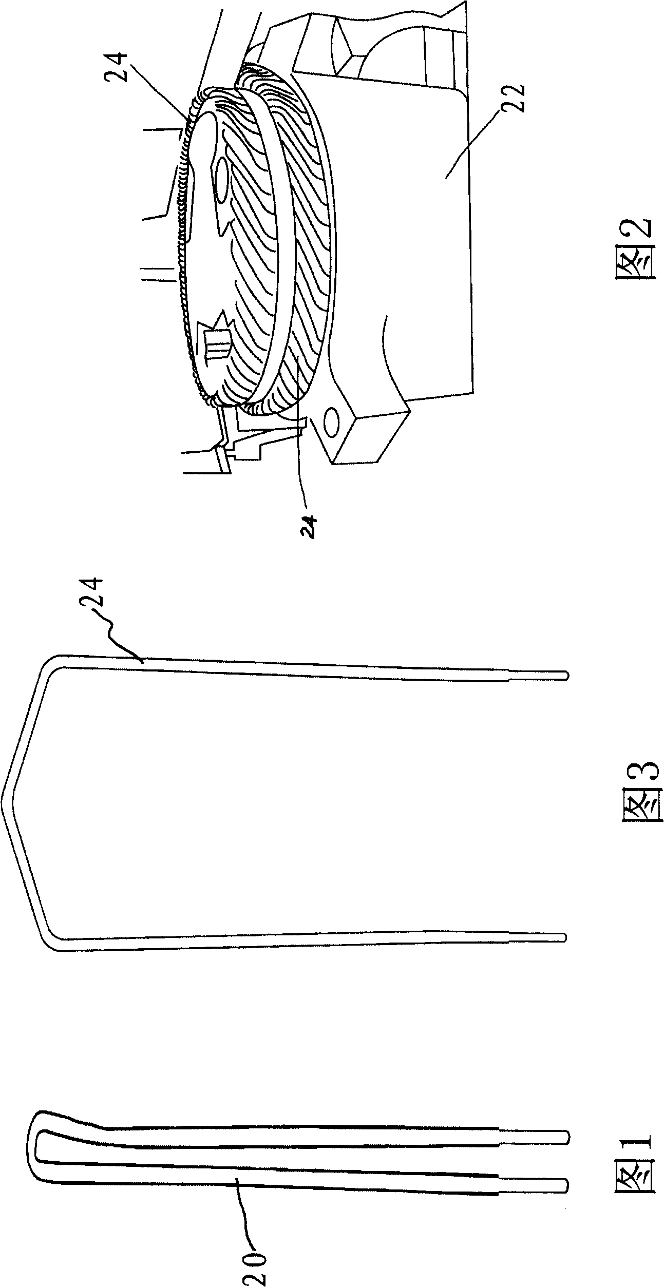
[0031] The object of the invention is to simultaneously remove all rectangular winding wires from the torsion jig and place the wires on the desired rotor or stator core. In particular, a rectangular insulated wire with stripped ends is bent to form a hairpin wire 20 as shown in FIG. 1 . Then, except for the special length stator wires used for the phase connection in AC motors, all the wires required are simultaneously bent into the rotor or stator wires 24 ( FIG. 3 ) in the torsion jig 22 shown in FIG. 2 . After the twisting operation, the wire 24 remains in the clamp 22, which has sufficient depth so that the end of the wire 24 is still located in the cavity within the clamp. The term "chamber" as used here is used in a general sense and includes not only enclosures enclosed on all sides, but also grooves which are open on one side.

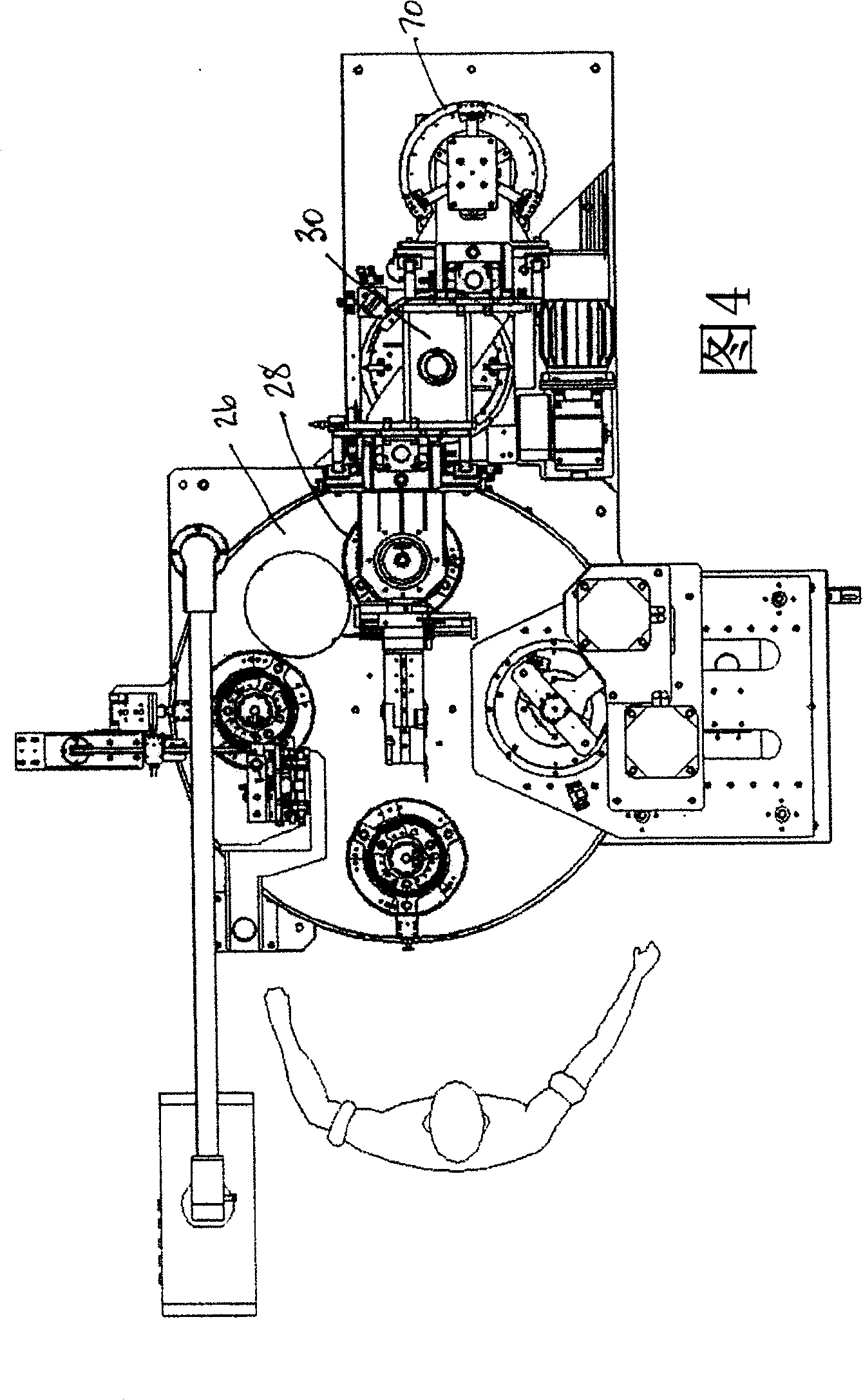
[0032] Figure 4 shows a top view of the entire system using the present invention. After the twisting operation, the table 26 is rotated so...


PUM


Abstract

The invention discloses a method for removing winding wires in a twister and placing in a rotor or a stator group and a device thereof. The method comprises: removing a plurality of rectangle winding wires from a twisting clamp and inserting thereof into the rotor and the stator, wherein each of the plurality of rectangle winding wires has a pair of support leg, the spaced distance of which is equal to that between the stator and the rotor with scheduled number, and the support leg is inserted into a slot and connected integratively on one end; removing finger like pieces of a plurality of clamping modules between the support leg of the plurality of winding wires of the twisting clamp; removing the clamping module in a direction away from the twisting clamp, to extract the winding wires from the twisting clamp; providing the relative movement of the clamping module and the stator or the rotor, to causing free ends of the winding wires to be inserted into the rotor or the stator; and removing the finger like pieces between the support legs of the plurality of winding wires.

Description

technical field [0001] The invention relates to the field of electrical machines. Background technique [0002] Tecnomatic S.P.A., the assignee of the present invention, has done a number of motor stators and DC motor rotors in the past using flat or square wire wound in coils. As used herein, "flat (rectangular)" or "square" conductors refer to conductors having four generally flat sides, each joined to an adjacent side by generally rounded edges. In the case of square wire, the wire can be formed into a square and then coated with conventional wire wound insulation, or in some cases pre-coated round wire rolled into a square. Where the wire is first squared by drawing or other means and then coated, even a small rounded edge will serve the purpose, but round wires are rolled into squares provided the insulation is not damaged method also has certain limitations. Even if the wire is first formed into the desired shape before being coated, some rounding on the edges is ne...

Claims


Application Information

Patent Timeline
Patent Type & Authority Applications(China)
IPC IPC(8): H02K15/08H02K3/46
CPCY10T29/49012Y10T29/49817Y10T29/49009H02K15/0428Y10T29/53157H02K15/063H02K15/064
Inventor 桑特·古尔奇奥尼
Owner TECNOMATIC
Why Eureka
Try Eureka