

Free-space optical communication device
A space communication and optical signal technology, applied in the direction of free space transmission, short-distance systems, electrical components, etc.
- Summary
- Abstract
- Description
- Claims
- Application Information
AI Technical Summary
Problems solved by technology
Method used
Image

Examples
Embodiment 1
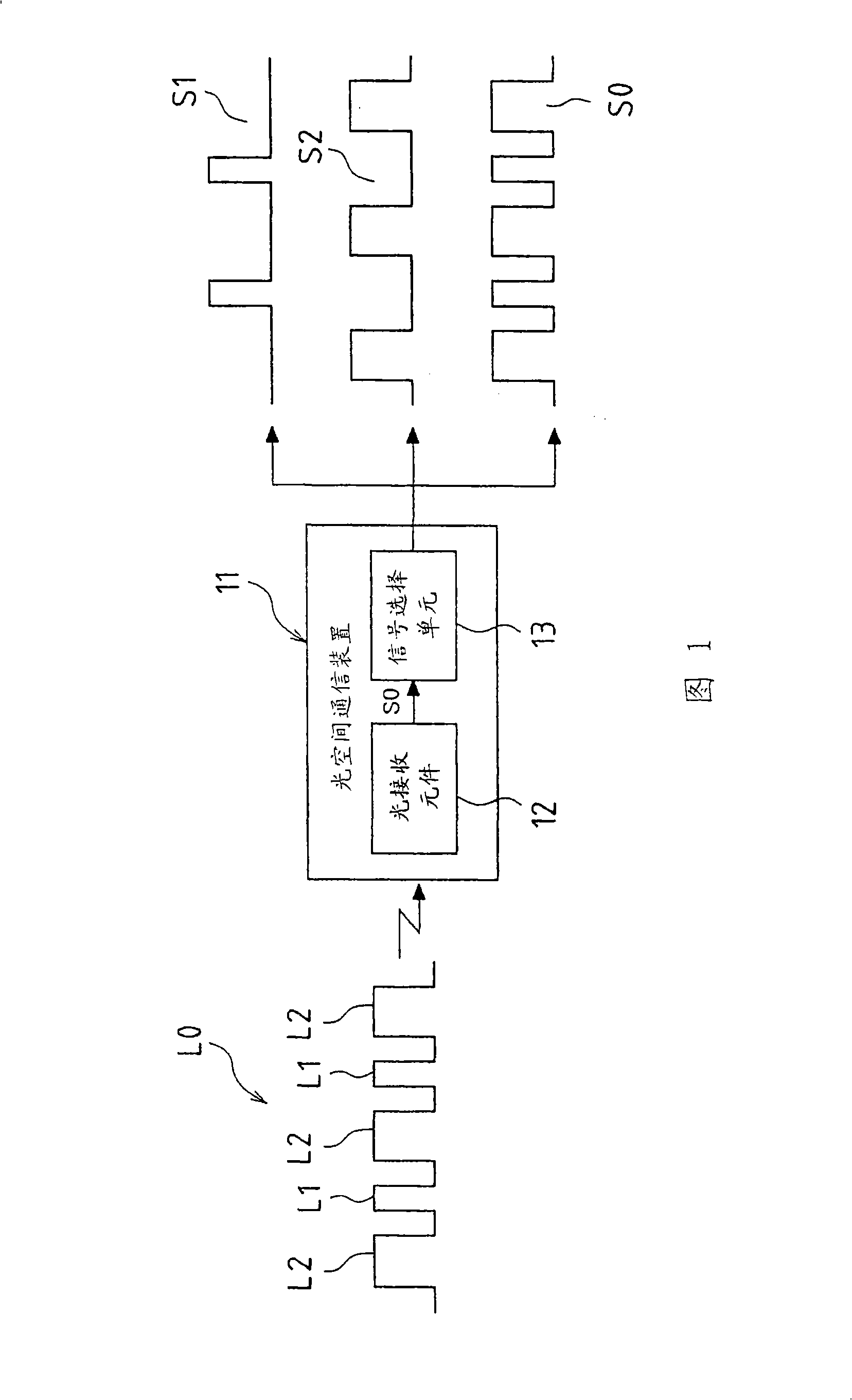
[0032] FIG. 1 is a block diagram showing Embodiment 1 of the optical space communication device of the present invention. The optical space communication device 11 of this embodiment includes a light receiving element 12 and a signal selection unit 13 . The light-receiving element 12 receives the communication signal L0, and photoelectrically converts the communication signal L0, which is the light-receiving signal, into an electrical signal S0. The communication signal L0 includes two kinds of infrared light signals L1 and L2 representing different information.
[0033] The infrared optical signals L1 and L2 are, for example, audio signals or music signals, and are optical signals pulse-width-modulated or pulse-density-modulated based on different pieces of information. Then, these infrared light signals L1 and L2 are time-divisionally synthesized to form a communication signal L0. Accordingly, the communication signal L0 includes infrared light signals L1 and L2 representi...
Embodiment 2
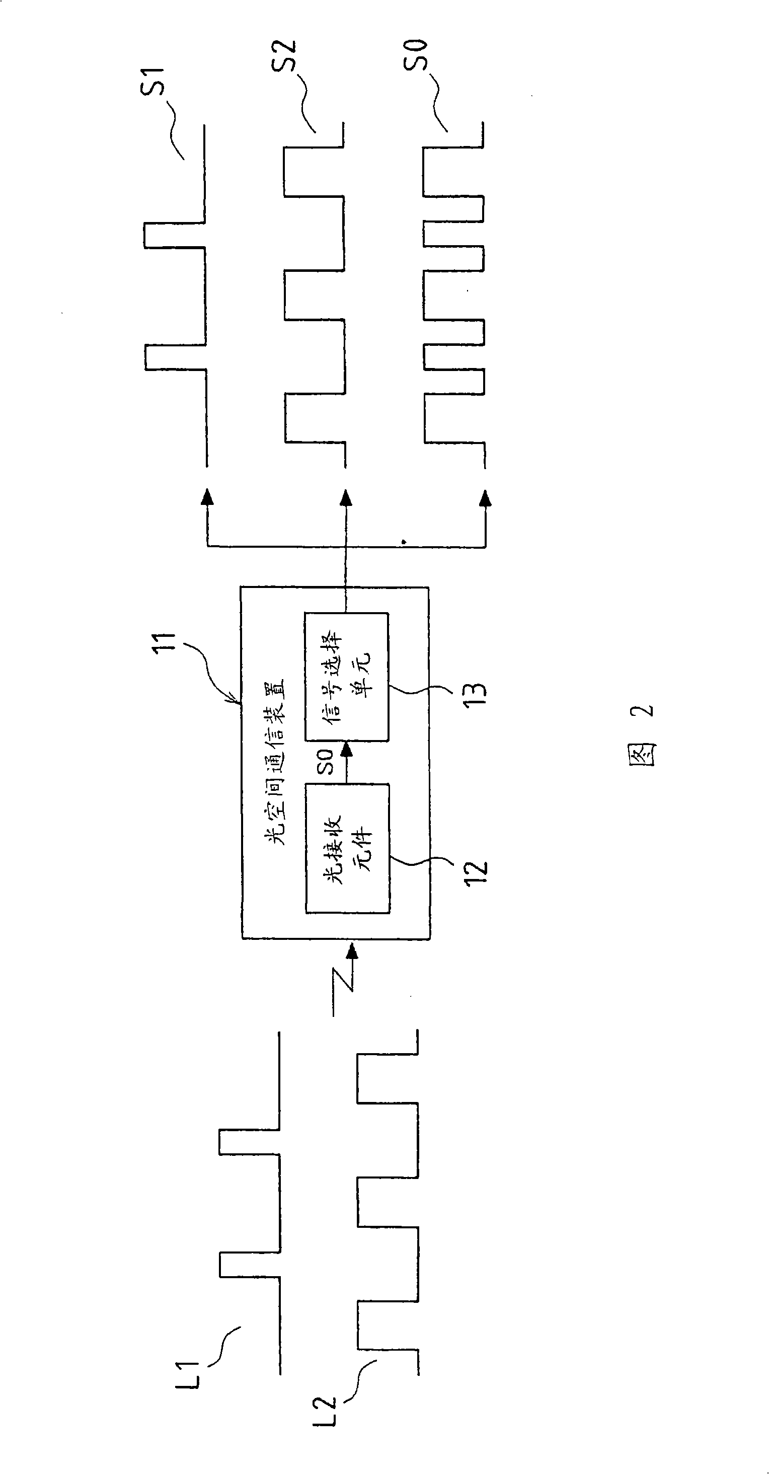
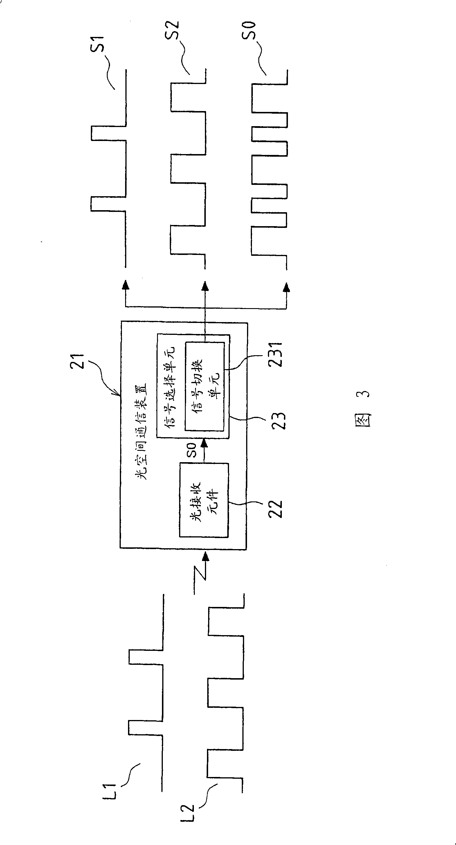
[0043] Fig. 3 is a block diagram showing Embodiment 2 of the optical space communication device of the present invention. The optical space communication device 21 of this embodiment includes a light receiving element 22 and a signal selection unit 23 . The light-receiving element 22 receives two kinds of infrared light signals L1 and L2 respectively representing different information, and photoelectrically converts these light-receiving signals, that is, the infrared light signals L1 and L2 into an electrical signal S0 . The signal selection unit 23 receives an electrical signal S0 from the light receiving element 22 , demodulates and separates the signal S1 and the signal S2 from the electrical signal S0 , and selectively outputs the signal S1 , the signal S2 , and the electrical signal S0 .
[0044] The illustrated signal selection unit 23 includes a signal switching unit 231 . Moreover, the signal switching unit 231 can select to output the signal S1 corresponding to the ...
Embodiment 3
[0049] Fig. 4 is a block diagram showing Embodiment 3 of the optical space communication device of the present invention. The optical space communication device 31 of this embodiment includes a light receiving element 32 and a signal selection unit 33 . The light-receiving element 32 receives two kinds of infrared light signals L1 and L2 respectively representing different information, and photoelectrically converts these light-receiving signals, that is, the infrared light signals L1 and L2 into an electrical signal S0 .
[0050] The signal selection unit 33 receives an electrical signal S0 from the light receiving element 32 , demodulates and separates the electrical signal S0 into a signal S1 and a signal S2 , and outputs the signal S1 , the signal S2 , and the electrical signal S0 .
[0051] The infrared optical signals L1 and L2 are optical signals subjected to pulse width modulation or pulse density modulation, and are transmitted respectively. Therefore, the modulation...
PUM
 Abstract
Description
Claims
Application Information