
Method for controlling sound output

A sound output and sound technology, applied in the direction of speaker distribution signal, transducer circuit, sensor, etc., can solve the problem that the sound output device cannot be controlled

Inactive Publication Date: 2011-03-16
KINPO ELECTRONICS
View PDF0 Cites 0 Cited by
  • Summary
  • Abstract
  • Description
  • Claims
  • Application Information

AI Technical Summary

Problems solved by technology

[0006] In order to improve the shortcomings of the known sound output devices that cannot be controlled, and provide wireless earphones and wired earphones to output sound at the same time, so that a single device can be used by two people at the same time; and must maintain the function of being able to switch, and propose the present invention

Method used


Image

  • Method for controlling sound output
  • Method for controlling sound output
  • Method for controlling sound output

Examples


Embodiment Construction

[0028] see Figure 4 shown. Implementation of the embodiment of the device used in the method of the present invention includes a microprocessor 40 electrically connected to the control panel 41, the power switch 32 of the wireless transmission module 30 and UART (Universal Asynchronous Receiver / Transmitter, Universal Asynchronous Receiver Transmitter), speaker 61 The sound signal switch 611 and the detection circuit 621 for plugging the plug of the wired earphone 62 into the socket. A sound source 50 is electrically connected to an amplifier 51, and the amplifier 51 is respectively electrically connected to the wireless transmission module 30, the sound signal switch 611, and the detection circuit 621 to provide sound output. The power supply 70 is electrically connected to the power switch 32 and provides power required by each component of the device. Wherein the power switch 32 and the sound signal switch 611 can be switches composed of transistors respectively.

[0029...


PUM


Abstract

When the user selects the exclusive mode, only one among the built-in speaker, the earphone and the wireless earphone can output voice. While the user selects the sharing mode, at least two of the built-in speaker, the earphone and the wireless earphone can simultaneously output voice. More choices raise the practical feature of the production.

Description

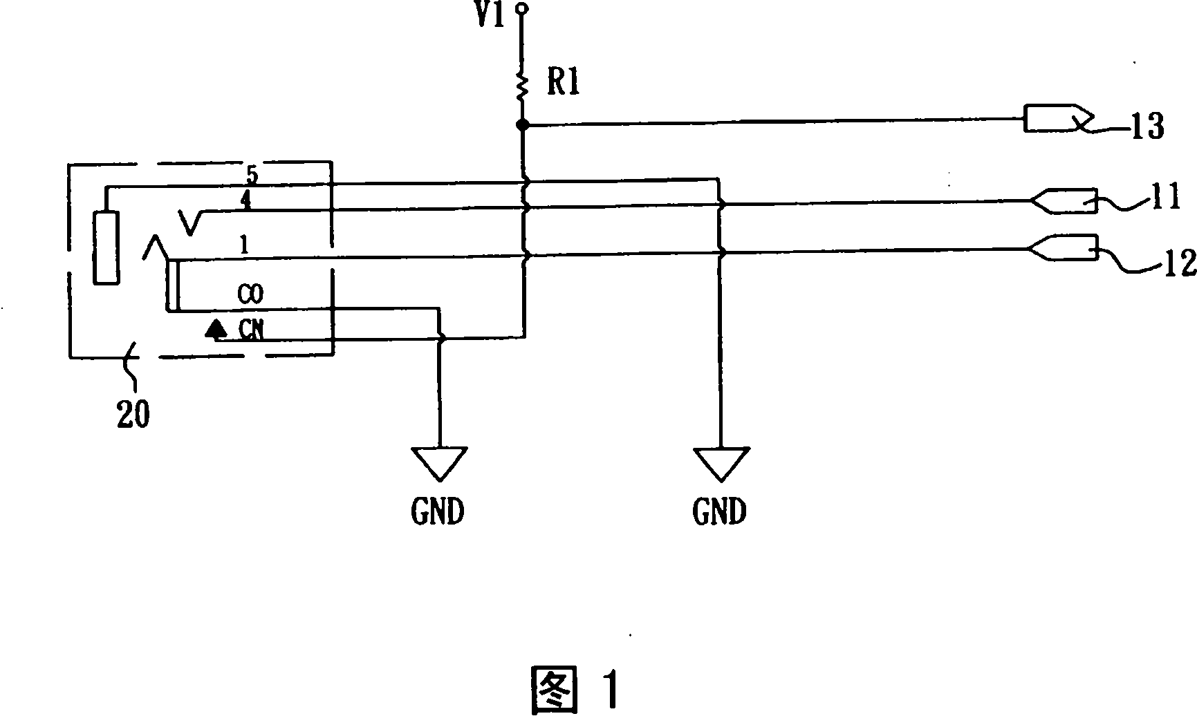
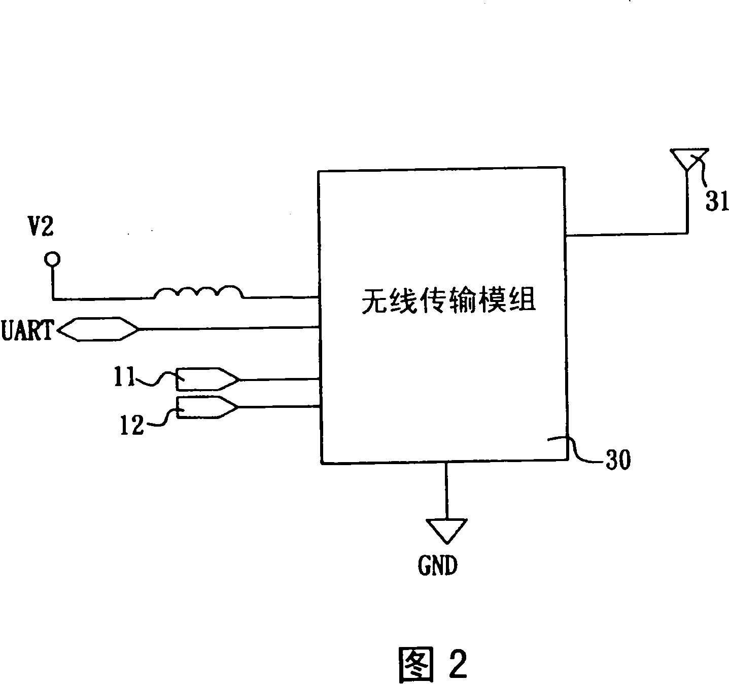
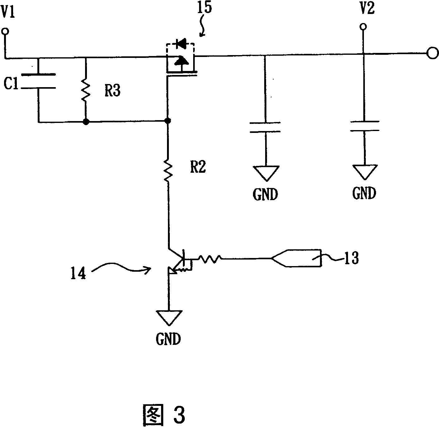
technical field [0001] The present invention relates to earphone connection interfaces of sound output devices such as audio devices, hand-held music devices, and mobile phones, and in particular to a method for controlling sound output of wireless earphones, wired earphones, and built-in speakers of the above-mentioned devices. Background technique [0002] In general audio-visual devices, the headphone socket is often used to detect the plug-in action to switch the speaker output device. When it is detected that the earphone plug is inserted, the speaker output is cut off, which is convenient for the user to switch the sound output device. [0003] see figure 1 , figure 2 , image 3 shown. Known sound output devices that simultaneously support wireless earphones and wired earphones are to electrically connect the left and right channel output terminals 11, 12 of the sound to the wired earphone socket 20 (such as figure 1 shown) and wireless transmission module 30 (su...

Claims


Application Information

Patent Timeline
Patent Type & Authority Patents(China)
IPC IPC(8): H04R3/00H04R3/12
Inventor 孙君意
Owner KINPO ELECTRONICS
Learn More