

Parking apparatus
The technology of a parking device and a parking board is applied in the field of a device for placing vehicles and a liftable and movable parking device, which can solve the problems of insufficient parking space and achieve the effects of low cost, simple structure and easy realization
- Summary
- Abstract
- Description
- Claims
- Application Information
AI Technical Summary
Problems solved by technology
Method used
Image

Examples
no. 1 example
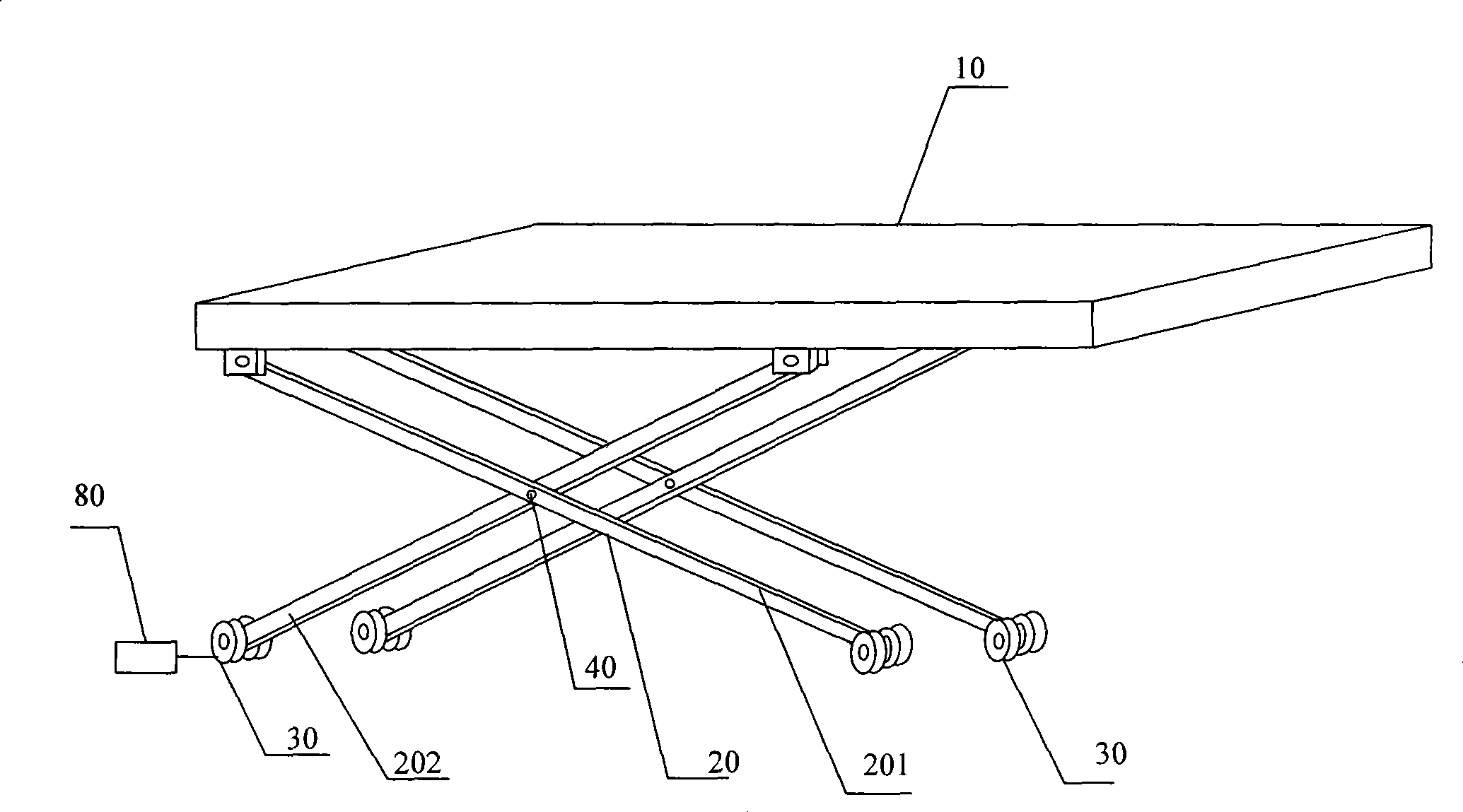
[0023] figure 1 It is a structural schematic diagram of the first embodiment of the parking device of the present invention. Such as figure 1 As shown, the parking device of the present embodiment includes a parking board 10, a support 20, and a driving device 80; the parking board 10 is used to place a vehicle; , the moving device can be a device that makes the bracket 20 move in parallel, and can use a roller or a slider. In this embodiment, a roller 30 is used to realize it; the driving device 80 is connected with the bracket 20, and is used to drive the bracket 20 to make the parking plate 10 lift or move.
[0024] Specifically, the parking board 10 is a rectangular flat plate, and there are at least two brackets 20 , and this embodiment uses two brackets as an example for illustration. Two supports 20 are respectively arranged along the long sides of the parking plate 10, so that the parking plate 10 can move along the long side direction of the parking plate 10; The ...
no. 2 example
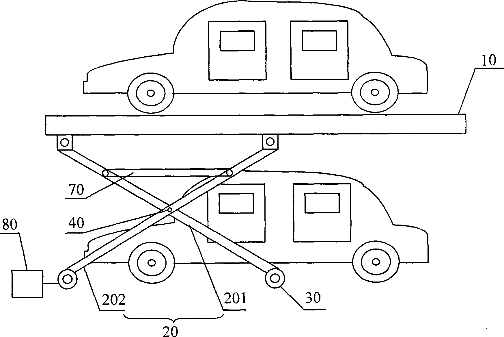
[0029] Figure 4 It is a structural schematic diagram of the second embodiment of the parking device of the present invention. The basic structure of this embodiment is basically the same as that of the first embodiment, the difference is that the upper end of the connecting rod 201 and the upper end of the connecting rod 202 are movable, and a driving device 81 is arranged on the upper end of the connecting rod 201 and the connecting rod Between the upper ends of 202, the parking plate 10 is raised or lowered by pulling or pushing the upper ends of the two connecting rods to move. Furthermore, the support 20 is connected to a further drive 82 for moving the parking device.
[0030] The working process of this embodiment is basically the same as that of the first embodiment. A driving device 81 is provided between the upper end of the connecting rod 201 and the upper end of the connecting rod 202 to move the two towards each other, so that the upper end of the connecting rod ...
no. 3 example
[0032] Figure 5 It is a structural schematic diagram of the third embodiment of the parking device of the present invention. Such as Figure 5 As shown, the parking device of the present embodiment includes a parking board 10, a support 90, and a driving device 83; the parking board 10 is used to place a vehicle; The moving device that drives the parking board to move adopts the roller 30 in this embodiment; the driving device 83 is connected with the bracket 90 and is used to drive the bracket 90 to make the parking board 10 lift or move.
[0033] Specifically, the parking board 10 is a rectangular plane board, and there are at least two brackets 90 . These two brackets 90 are arranged along the short sides of the parking board 10 respectively, so that the parking board 10 can move along the short side direction of the parking board 10; Rod 902, two connecting rods 901 are respectively hinged with two connecting rods 902 through two hinge shafts 40, the lower end of the l...
PUM
 Abstract
Description
Claims
Application Information