
Field interpolation method

A technology of interpolation and interpolation direction, applied in the field of video processing, which can solve the problems of small-angle interpolation pixels that are far apart, flickering, and easy to introduce isolated point noise.

Inactive Publication Date: 2009-05-27
SICHUAN PANOVASIC TECH
View PDF0 Cites 5 Cited by
  • Summary
  • Abstract
  • Description
  • Claims
  • Application Information

AI Technical Summary

Problems solved by technology

[0005] 1. Insufficient selection of direction may easily produce sawtooth;
[0006] 2. Small-angle interpolation is easy to introduce isolated point noise because the selected pixels are far apart;
[0007] 3. Image areas with rich details flicker after edge interpolation

Method used


Image

  • Field interpolation method

Examples


Embodiment Construction

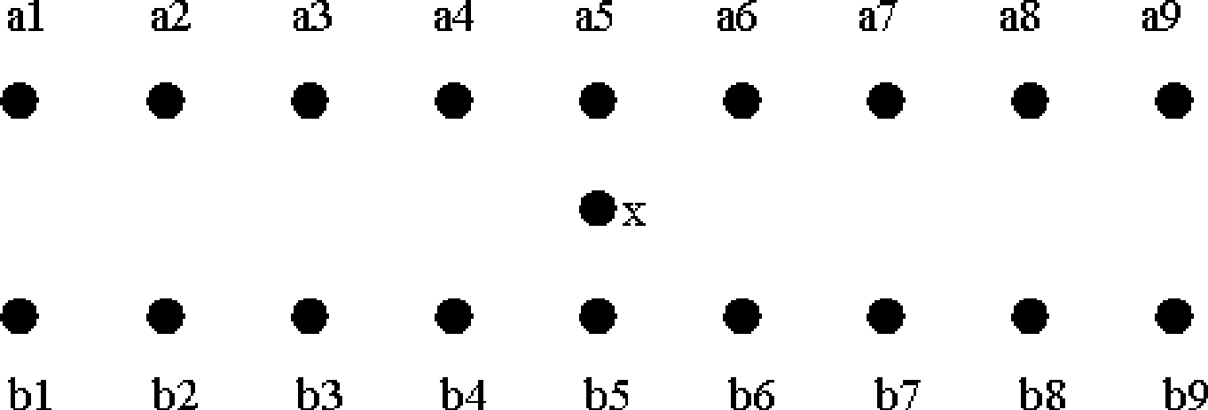
[0031] 1. Pixel grayscale information existing in the upper and lower rows of the point to be interpolated (such as figure 1 As shown, the gray values ​​of the 9 adjacent pixels in the upper row are a1, a2, a3, a4, a5, a6, a7, a8, a9 from left to right, and the gray values ​​of the 9 adjacent pixels in the lower row are from From left to right, b1, b2, b3, b4, b5, b6, b7, b8, b9, the point to be interpolated x) calculates the pixel correlation in nine directions, and the pixel correlation of the direction is calculated by calculating the corresponding pixel points in different directions The average performance of the absolute difference sum of gray levels, a total of nine directions, the first direction to the ninth direction (10°, 20°, 45°, 60°, 90°, 120°, 135°, 160°, 170°) The average value of the absolute difference sum of the gray value of the pixel is p1, p2...p9 respectively:

[0032] p1: (|a7-b1|+|a8-b2|+|a9-b3|) / 3

[0033] p2: (|a6-b3|+|a7-b4|) / 2

[0034] p3: (|a5-...


PUM


Abstract

The invention relates to video processing technology, in particular to technology of converting an interlaced video signal to a progressive video. The invention provides a field interpolation method which considers more angle pixel correlation to determine the interpolation direction and can eliminate the noise of isolated points, and a reference angle has nine directions which are divided into four small angle directions and five adjacent directions. In certain areas with small gap of pixel correlation, if a small angle is selected for interpolation, noise spots can be introduced into the area, so a small angle factor can not be considered to select the direction with maximum pixel correlation from the five adjacent directions for the interpolation as long as the pixel correlation of the adjacent directions achieves a first preset value; if the small angle is considered, whether the pixel correlation of a direction of an supplementary angle of the small angle is less than a second preset value also needs to be judged, if yes, the small angle is selected and if not so, the direction with the maximum pixel correlation is selected from the five adjacent directions for the interpolation. The video processing technology can obtain an interpolation result with smooth edges and flicker-free details.

Description

technical field [0001] The invention relates to a video processing technology, in particular to a technology for converting an interlaced video signal to a progressive video. technical background [0002] Due to the limitation of transmission bandwidth, the TV signals sent by TV stations are not complete images, but a scene is divided into two parts, odd field and even field, and sent in time-sharing, thus generating interlaced video signals. However, with the continuous development of digital signal processing technology and the emergence of wide-screen flat-panel TVs, people's requirements for TV display quality are getting higher and higher. When the interlaced signals sent by TV stations are displayed on current high-end flat-panel TVs, severe screen flicker will occur. , sawtooth and other serious problems. De-interlacing technology was created to solve the conflict between interlaced video signals and high-end TVs. [0003] The de-interlacing algorithm is divided int...

Claims


Application Information

Patent Timeline
IPC IPC(8): H04N7/01
Inventor 刘强陈涛
Owner SICHUAN PANOVASIC TECH
Learn More