Transformer operation control apparatus and method for suppressing magnetizing inrush current

An operation control, transformer technology, applied in the direction of emergency protection circuit device, circuit device, emergency protection circuit device for limiting overcurrent/overvoltage, etc., can solve the offset, circuit breaker closing action time error, pre-arc time errors, etc.

Inactive Publication Date: 2009-06-03
MITSUBISHI ELECTRIC CORP
View PDF2 Cites 18 Cited by
  • Summary
  • Abstract
  • Description
  • Claims
  • Application Information

AI Technical Summary

Problems solved by technology

[0006] In the prior art, due to the error of the closing action time of the circuit breaker and the error of the pre-arcing time, the first turn-on time of the first turn-on current of the three phases and the target turn-on time can cause deviations

Method used


Image

  • Transformer operation control apparatus and method for suppressing magnetizing inrush current
  • Transformer operation control apparatus and method for suppressing magnetizing inrush current
  • Transformer operation control apparatus and method for suppressing magnetizing inrush current

Examples


Embodiment 1

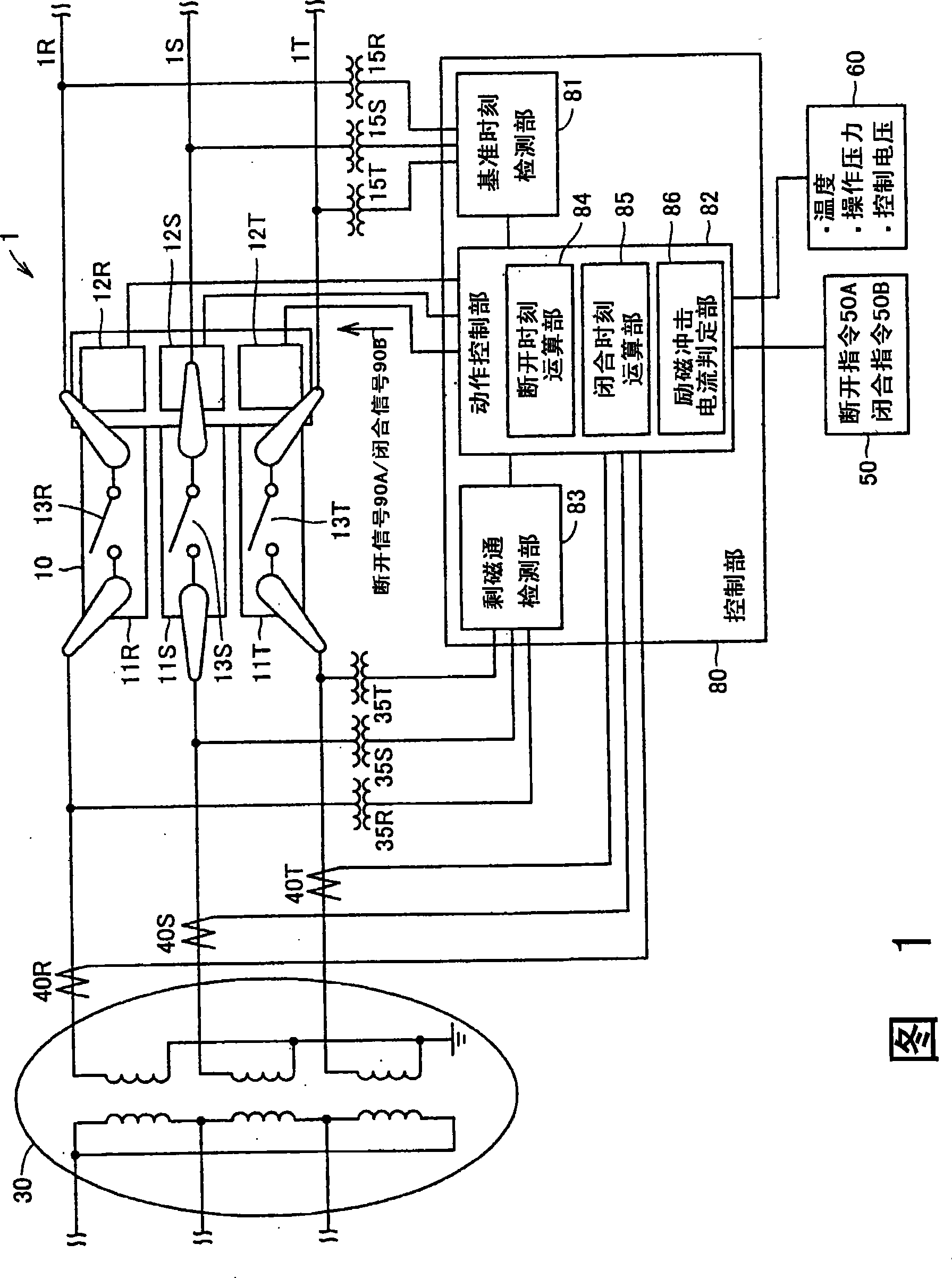
[0024] Fig. 1 is a block diagram showing the composition of a transformer operation control device 1 according to Embodiment 1 of the present invention. Referring to FIG. 1 , a transformer operation control device 1 includes a transformer 30 and a circuit breaker 10 .

[0025] The transformer 30 is a three-phase transformer connected in Y-Δ connection. Specifically, the windings on the power supply side of the transformer 30 are connected in a Y connection with the neutral point grounded, and the windings on the load side are connected in a delta connection.

[0026] The circuit breaker 10 is connected between the line of the power system including each phase of the R phase 1R, the S phase 1S, and the T phase 1T, and the transformer 30 . The circuit breaker 10 includes: arc extinguishing chambers 11R, 11S, 11T provided with the contacts 13R, 13S, 13T; and operating devices 12R, 12S, 12T for switching the contacts 13R, 13S, 13T. In order to independently switch the contacts 1...

Embodiment 2

[0091] Example 2 differs from Example 1 in the determination conditions for confirming the suppression effect of the field inrush current. In the second embodiment, the on-time T1on of the current of the first on-phase is actually detected, and the deviation from the target on-time T1target is determined. When the difference between the actual on-time T1on and the target on-time T1target is not within the allowable range, since the residual magnetic flux of the first on-phase at the time of turning on is different from the steady magnetic flux, an excitation inrush current is generated.

[0092] FIG. 9 is a block diagram showing the structure of a transformer operation control device 1A according to Embodiment 2 of the present invention. The operation control device 1A of FIG. 9 is different from the operation control device of FIG. 1 in that an on-time determination unit 87 is included instead of the field inrush current determination unit 86 . Furthermore, the operation con...


PUM


Abstract

The invention discloses a transformer operation control apparatus and method for suppressing magnetizing inrush current. A control portion 80 for a breaker 10 causes the breaker 10 to apply a current of a first apply phase (R phase) at a timing where a residual flux of R phase agrees with a steady magnetic flux. Thereafter, the control portion 80 determines whether or not the current measured by current measuring portions 40R, 40S, 40T exceeds a threshold value. When the measured current does not exceed the threshold value, the control portion 80 causes the breaker 10 to apply currents of the other two phases (S and T phases) at a timing where a voltage of R phase becomes zero. When the measured current exceeds the threshold value, the control portion 80 causes the breaker 10 to once shut off the current of R phase and to apply again the current of R phase.

Description

technical field [0001] The present invention relates to an operation control device and method for suppressing excitation surge current transiently flowing through the transformer when the transformer is connected to the power system. Background technique [0002] In order to suppress the excitation inrush current, it is very important to control the moment when the transformer turns on the current. [0003] In the technique described in Japanese Patent Laid-Open No. 2004-208394, the voltage on the transformer side of the circuit breaker is integrated for each phase to calculate the magnetic flux signal, and the convergence of the voltage on the transformer side after the input of the opening command is calculated. The difference between the magnetic flux value at the moment of zero value and the central value of the magnetic flux signal before the input of the opening command is regarded as the residual magnetic flux. Then, the phase in which the absolute value of the resi...

Claims


Application Information

Patent Timeline
Patent Type & Authority Applications(China)
IPC IPC(8): H02H7/04H02J3/00
CPCH02H9/002
Inventor 木下定之龟井健次森智仁
Owner MITSUBISHI ELECTRIC CORP
Why Eureka
Try Eureka