Spinous process spacer

A spacer and spinous process technology, applied in the direction of spinal implants, internal fixators, internal bone synthesis, etc., can solve the problems of unstable contact state, large gap opening angle between divided spinous processes, collisions, etc. Achieve the effect of cheap manufacturing and simple shape

Inactive Publication Date: 2009-06-17
OLYMPUS TERUMO BIOMATERIALS
View PDF0 Cites 10 Cited by
  • Summary
  • Abstract
  • Description
  • Claims
  • Application Information

AI Technical Summary

Problems solved by technology

[0009] When a single spinous process spacer is applied to all patients, depending on the patient, the opening angle of the gap between the divided spinous processes becomes larger, and the gap between the spinous process spacer and the two dividing planes that divide the spinous processes is different. Undesirable conditions where a wedge-shaped gap is formed
In this case, the cut surface of the spinous process and the spacer of the spinous process come into contact with an extremely narrow contact area, and the contact state is unstable, and there is a possibility that it may deviate over time after the operation
Also, with trapezoidal spacers, when the neck is stretched, the spacers placed up and down may rotate and collide with each other or interfere with the spinal cord

Method used


Image

  • Spinous process spacer
  • Spinous process spacer
  • Spinous process spacer

Examples


Embodiment Construction

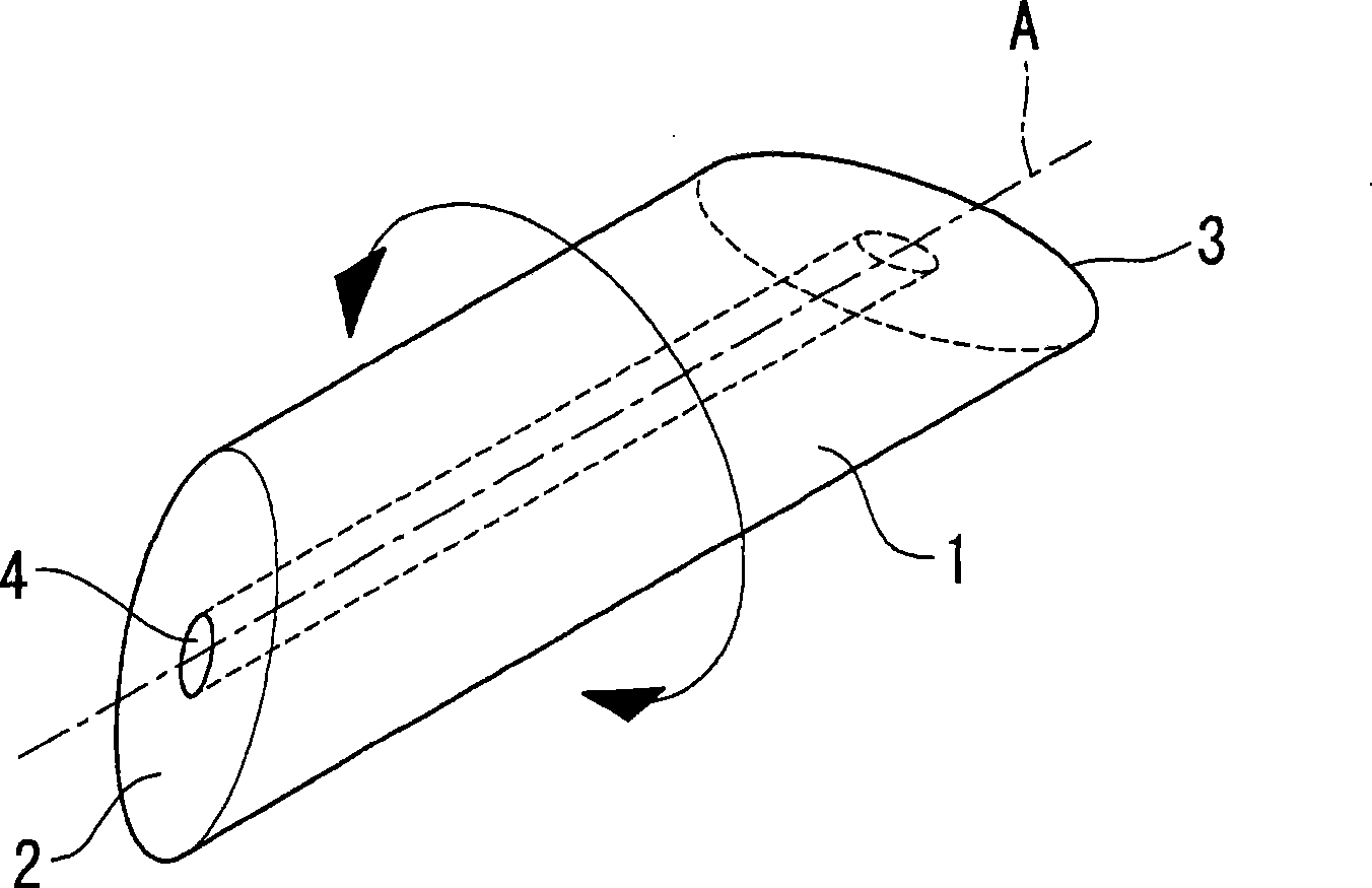
[0049] Below, refer to Figure 1 to Figure 5The spinous process spacer 1 according to the first embodiment of the present invention will be described.

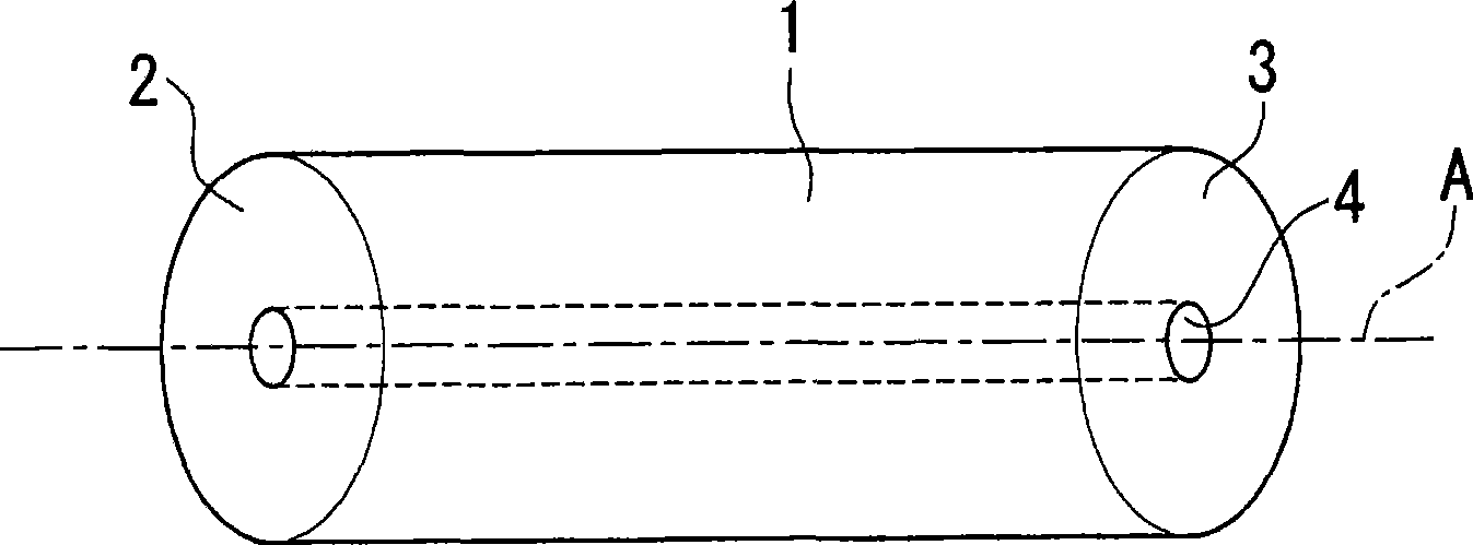
[0050] like figure 1 As shown, the spinous process spacer 1 of the present embodiment is formed of columnar calcium phosphate, and its both end faces 2 and 3 have a form inclined with respect to the central axis A.

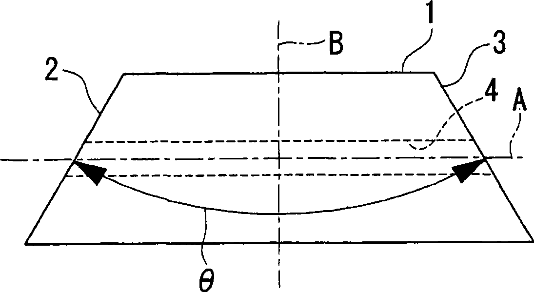
[0051] like figure 2 As shown, the above-mentioned end faces 2, 3 are composed of planes inclined in opposite directions with respect to the central axis A at the same angle. Therefore, the spinous process spacer 1 of the present embodiment is mirror-symmetrical about a plane B passing through the center in the longitudinal direction and perpendicular to the central axis A. The angle θ formed by the two end surfaces 2 and 3 is set to, for example, one angle selected from the range of 30° to 90°.

[0052] As a result, when from figure 2 The spinous process spacer 1 of this embodiment has a trapezoidal cross-...


PUM


Abstract

A spinous process spacer that without being fabricated on a made-to-order basis for each patient, realizes stable insertion fixing in a division plane interspace of divided spinous process with no gap. There is provided spinous process spacer (1) for insertion in divided spinous process interspace resulting from longitudinal division of the spinous process, comprised of a plane formed into an approximately circular cylinder, the plane having two end faces (2,3) with a given angle therebetween.

Description

technical field [0001] The present invention relates to a spinous process spacer inserted between divided spinous processes obtained by longitudinally dividing the spinous processes of a cervical vertebra. Background technique [0002] Conventionally, in order to remove the obstacle caused by cervical spondylotic myelopathy or the ossification of the posterior longitudinal ligament compressing the spinal cord, spinal canal enlargement is performed. In the incision method, a spinous process spacer is inserted between the divided spinous processes formed by longitudinally dividing the spinous process (for example, refer to Patent Document 1). [0003] As a spinous process spacer used in this spinous process slitting method, Patent Document 1 discloses that both cross sections (horizontal cross section and longitudinal forehead cross section) in two mutually orthogonal directions are formed in a substantially trapezoidal block shape the spinous spacer. [0004] Spinous proces...

Claims


Application Information

Patent Timeline
Patent Type & Authority Applications(China)
IPC IPC(8): A61F2/44
CPCA61B17/7071A61F2/44
Inventor 柴田浩一入江洋之浦田光也小岛聪
Owner OLYMPUS TERUMO BIOMATERIALS
Why Eureka
Try Eureka