
Connector and electronic device

A technology for electronic devices and connectors, applied in the direction of connection, coupling device, circuit, etc., can solve the problems that general products do not have suitable structure, cost or user burden, occupy more space, etc.

Inactive Publication Date: 2012-09-26
ACER INC
View PDF7 Cites 6 Cited by
  • Summary
  • Abstract
  • Description
  • Claims
  • Application Information

AI Technical Summary

Problems solved by technology

[0002] In response to the development of mobile communication technology, in addition to the SIM card used in mobile phones, Micro SIM cards have also been developed in recent years for specific smart phones. However, because the size of Micro SIM cards is smaller than that of SIM cards, the corresponding connection The connector specifications are also different. Although Micro SIM cards also have adapter cards that can be used for SIM card connectors, purchasing additional adapter cards will easily cause a burden on users, both in terms of cost and use. The mobile phone needs to be equipped with connectors for SIM card and Micro SIM card at the same time, which will also take up more space
[0003] It can be seen that the above-mentioned existing connectors and electronic devices obviously still have inconvenience and defects in structure and use, and need to be further improved urgently.
In order to solve the above-mentioned problems, the relevant manufacturers have tried their best to find a solution, but for a long time no suitable design has been developed, and the general product has no suitable structure to solve the above-mentioned problems. This is obviously the relevant industry. Urgent problem

Method used


Image

  • Connector and electronic device
  • Connector and electronic device
  • Connector and electronic device

Examples


Embodiment Construction

[0037] In order to further explain the technical means and effects of the present invention to achieve the intended purpose of the invention, the specific implementation, structure, characteristics and features of the connector and electronic device proposed according to the present invention will be described below in conjunction with the accompanying drawings and preferred embodiments. Efficacy, detailed as follows.

[0038] Below in conjunction with accompanying drawing and two embodiments the present invention is described in detail:

[0039] Before the present invention is described in detail, it should be noted that in the following description, similar components are denoted by the same numerals.

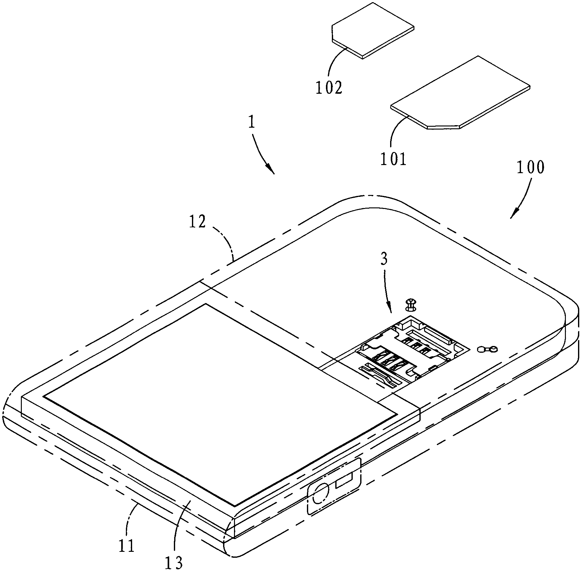
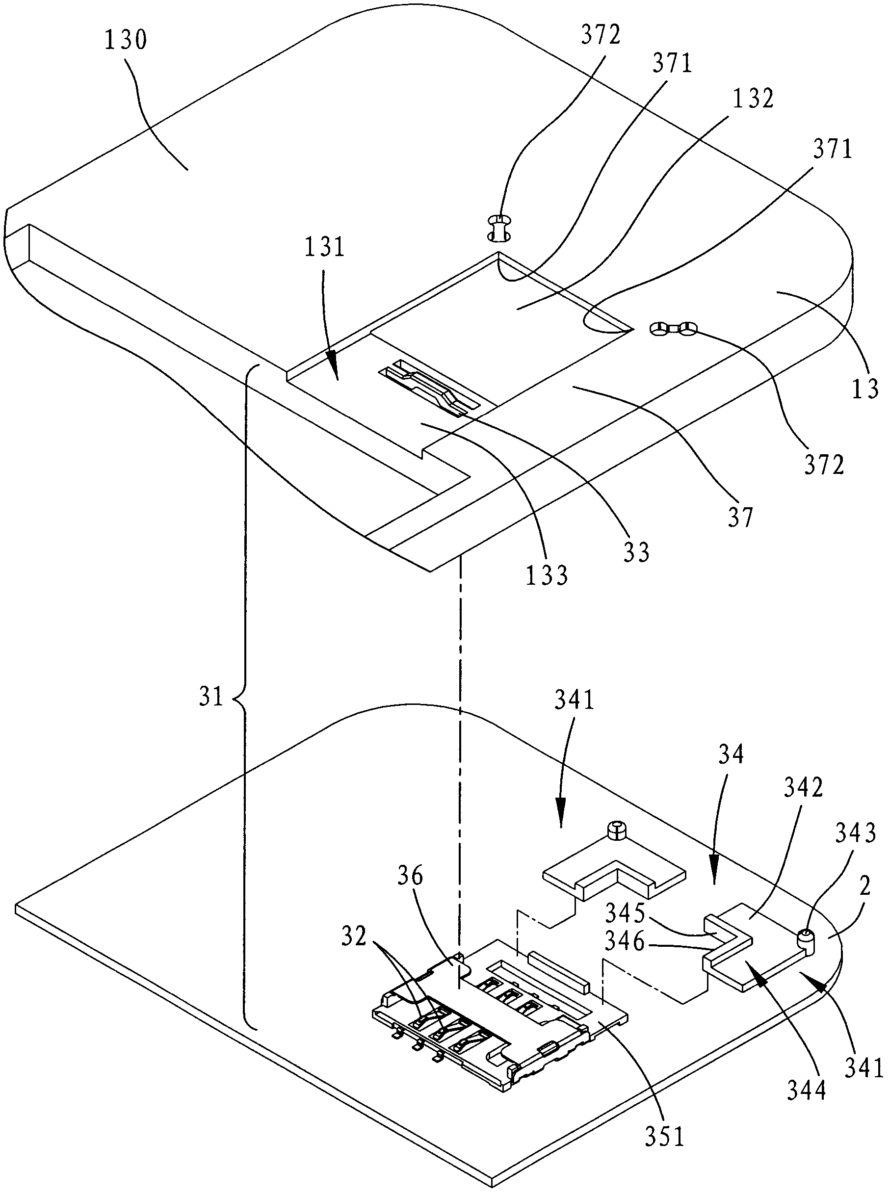
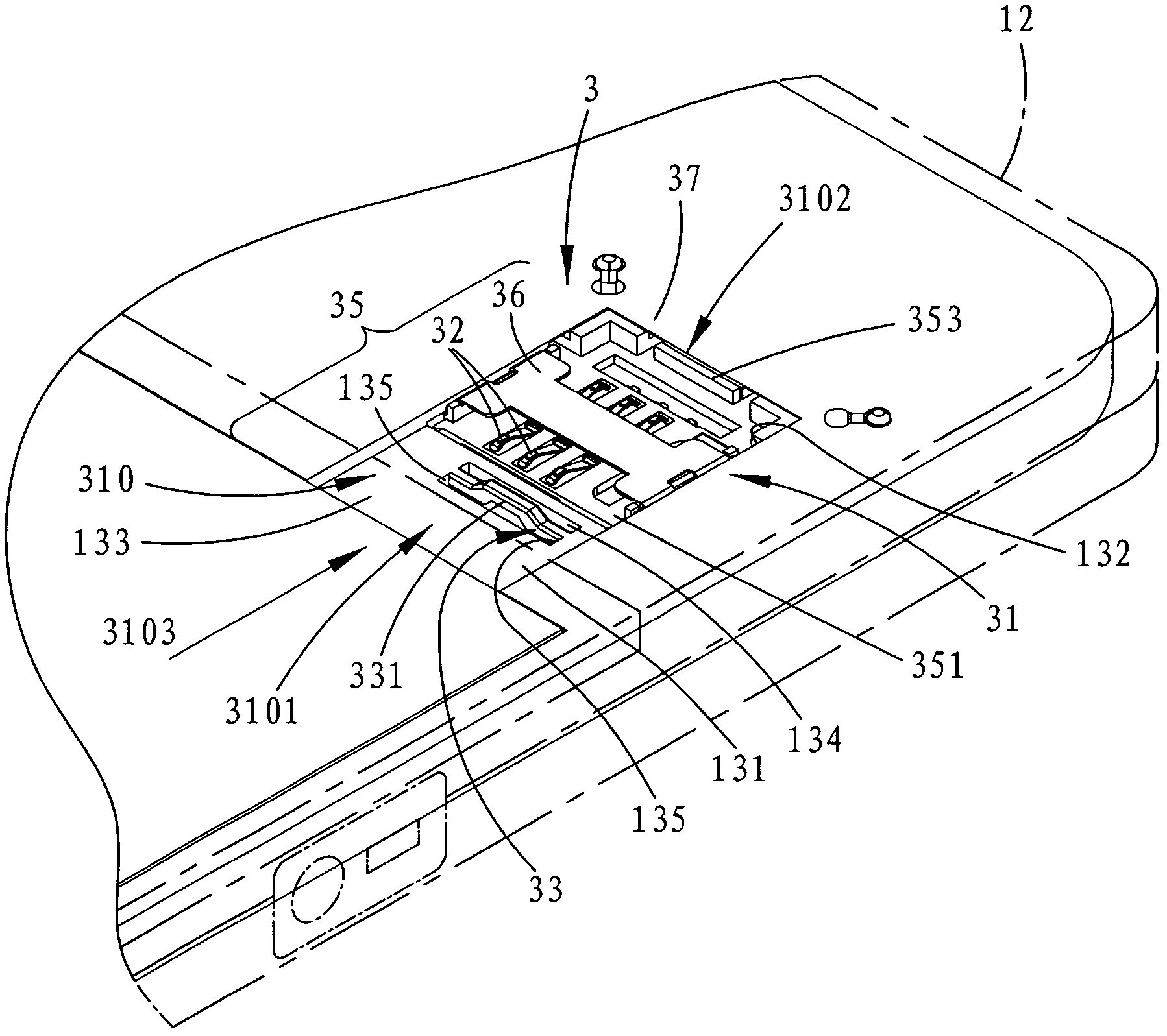
[0040] refer to Figure 1 to Figure 3 , the first preferred embodiment of the electronic device 100 of the present invention is a mobile phone, which includes a casing 1, a screen arranged on the casing 1, a circuit unit and a connector 3, and the casing 1 includes a front s...


PUM


Abstract

The invention relates to a connector and an electronic device. The electronic device comprises a shell and a connector. The connector comprises a base unit, a terminal set, an elastic stopper and a limit unit, wherein the base unit is arranged in the shell and defines an accommodating groove, the accommodating groove is provided with an inserting end and an inner end opposite to the inserting end, the terminal set is arranged in the base unit and exposed out of the accommodating groove, the elastic stopper is arranged in the base unit and located between the inserting end and the inner end, the limit unit is arranged in at the part, adjacent to the inner end, of the base unit and can be operated to move at a first position and a second position, and when the limit unit is at the first position, an SIM (subscriber identity module) card can be inserted in the accommodating groove and located between the inserting end and the inner end, and when the limit unit is at the second position, the limit unit extends to the inside of the accommodating groove from the inner end, so that a Micro SIM card can be inserted in the accommodating groove and props against a position between the limit unit and the elastic stopper.

Description

technical field [0001] The invention relates to a connector and an electronic device with the connector, in particular to a connector capable of inserting an electronic card and an electronic device with the connector. Background technique [0002] In response to the development of mobile communication technology, in addition to the SIM card used in mobile phones, Micro SIM cards have also been developed in recent years for specific smart phones. However, because the size of Micro SIM cards is smaller than that of SIM cards, the corresponding connection The connector specifications are also different. Although Micro SIM cards also have adapter cards that can be used for SIM card connectors, purchasing additional adapter cards will easily cause a burden on users, both in terms of cost and use. The mobile phone needs to be equipped with connectors for inserting SIM card and Micro SIM card at the same time, which also takes up a lot of space. [0003] It can be seen that the a...

Claims


Application Information

Patent Timeline
IPC IPC(8): H01R27/00H01R12/71H04M1/02
Inventor 洪佑宗
Owner ACER INC
Learn More