Manual and automatic control axial flow distribution reversing rotary valve

A flow distribution valve and flow distribution technology, applied in valve details, multi-way valves, valve devices, etc., can solve the problems of normal production and operation, difficult balance of rotary valves, single control mode, etc., to achieve good sealing, flexible rotation, and use convenient effect

Active Publication Date: 2010-04-21
宁波市博尔法液压有限公司
View PDF3 Cites 0 Cited by
  • Summary
  • Abstract
  • Description
  • Claims
  • Application Information

AI Technical Summary

Problems solved by technology

[0002] Rotary valve is a control element that changes the direction of fluid movement by rotating the spool. At present, most domestic and foreign rotary valves use radial flow distribution, but the control method is single and can only be operated manually. The force effect is not easy to balance, so manual operation is particularly laborious and labor-intensive. In addition, the valve core is under the action of radial unbalanced force, which increases the wear between the valve core and the valve body, and the wear cannot be compensated, so the sealing performance is poor. Leakage accidents have multiplied, which has greatly affected the normal production and operation of users

Method used


Image

  • Manual and automatic control axial flow distribution reversing rotary valve
  • Manual and automatic control axial flow distribution reversing rotary valve
  • Manual and automatic control axial flow distribution reversing rotary valve

Examples


Embodiment Construction

[0014] Embodiments of the present invention will be further described below in conjunction with the accompanying drawings.

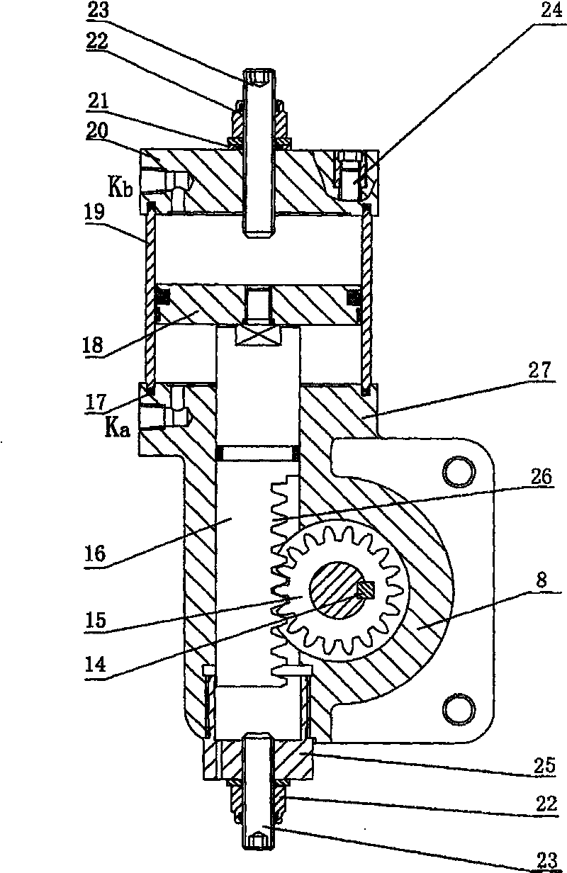
[0015] There is a screw hole in the middle of the cylinder head 20, and a sealing ring 21, a lock nut 22, and a stroke adjustment screw 23 are installed. There are mounting screw holes on the four opposite corners, a ring groove on the bottom surface, and an air intake or exhaust on the side wall. Hole Kb.

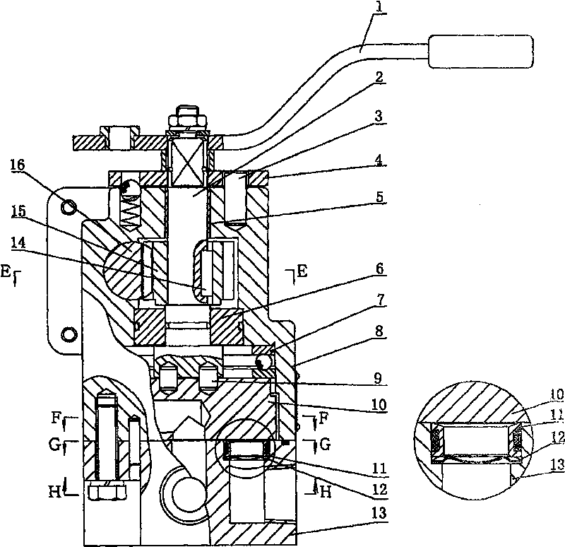
[0016] One side of the upper valve body 8 is a square flange 27. There is a guide hole in the middle of the square flange 27, and a ring groove is arranged on the edge. There is an eccentric distance between the guide hole and the vertical center hole of the upper valve body. The side wall of the square flange There are air intake or exhaust holes Ka.

[0017] There is a rack 26 on one side of the lower end of the piston rod 16, and the piston rod passes through the guide hole on the upper valve body 8 to mesh with the gear 15 on the rotating shaft ...


PUM


Abstract

The invention discloses a reversing rotary valve which manually and automatically controls coaxial flow distribution and comprises an automatic control device fixedly arranged on an upper valve body,connecting a cylinder cover, a cylinder barrel and the upper valve body into a self control body by the bolts of a pull rod and arranged in the self control body; the automatic control device comprisesthe cylinder cover, the cylinder barrel, a piston rod provide with a piston, a rotating shaft, a flow distribution valve core, the upper valve body and a lower valve body; one end of the piston rodis fixedly arranged on the piston, and the other end is provided with a rack which is meshed with a gear connected on the rotating shaft; the piston and the cylinder barrel are matched in a sliding way; the rotating shaft is connected with the flow distribution valve core by a transmission pin; the flow distribution valve core and a valve holder provided with a waveform spring to form plane seal and carry out coaxial flow distribution. The reversing rotary valve has good seal performance and non leakage; the wear clearance of the valve holder after working for a long time can be automaticallyadj usted and complemented; an automatic control device is additionally arranged to realize automatization, thus lightening the working intensity and improving the working efficiency; meanwhile, the steering rotary valve also has the manual control function, can be manually operated, controlled and interfered for emergency during power off, failure and debugging; the control functions thereof are complete; moreover, the valve is convenient and reliable for use.

Description

technical field [0001] The invention relates to a reversing rotary valve, especially one used in the hydraulic control system of petroleum blowout preventer to change the direction of fluid delivery, and adopts axial flow distribution and automatic control, and can be used in the event of power failure or failure. Manual and automatic control axial distribution reversing rotary valve for manual emergency operation. Background technique [0002] Rotary valve is a control element that changes the direction of fluid movement by rotating the spool. At present, most domestic and foreign rotary valves use radial flow distribution, but the control method is single and can only be operated manually. The force effect is not easy to balance, so manual operation is particularly laborious and labor-intensive. In addition, the valve core is under the action of radial unbalanced force, which increases the wear between the valve core and the valve body, and the wear cannot be compensated, ...

Claims


Application Information

Patent Timeline
Patent Type & Authority Patents(China)
IPC IPC(8): F16K11/00F16K31/14
Inventor 竺浩君潘若辰
Owner 宁波市博尔法液压有限公司
Why Eureka
Try Eureka