A support device and method for compensation of patient weight

A patient, axial location technique, applied in specific areas, that can address issues such as deviated tumors

Active Publication Date: 2009-07-15
QFIX SYSTEM LLC
View PDF1 Cites 17 Cited by
  • Summary
  • Abstract
  • Description
  • Claims
  • Application Information

AI Technical Summary

Problems solved by technology

If the highly tuned beam is a few millimeters off target, it can miss the tumor entirely

Method used


Image

  • A support device and method for compensation of patient weight
  • A support device and method for compensation of patient weight
  • A support device and method for compensation of patient weight

Examples


Embodiment Construction

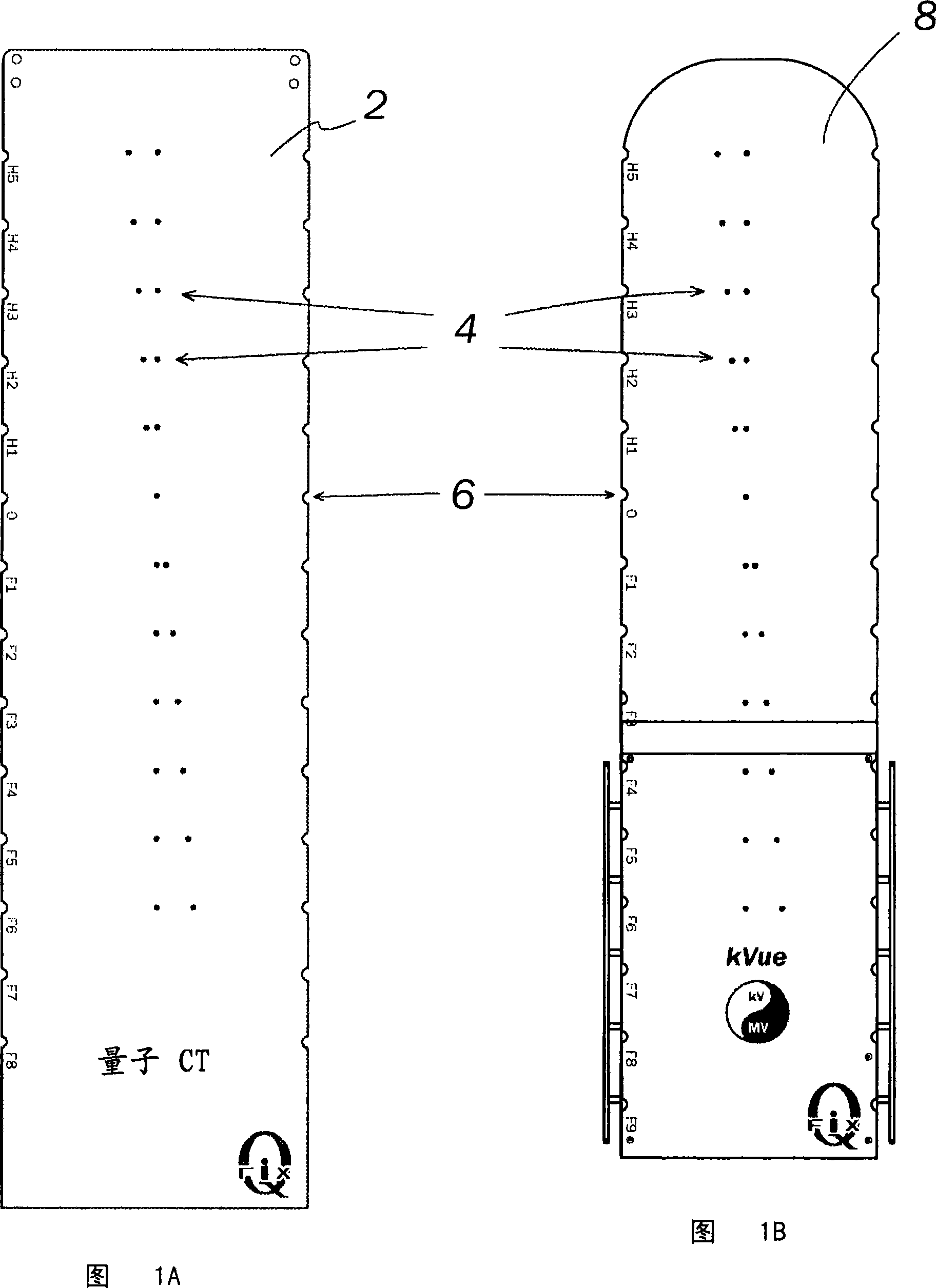
[0022] In both simulation and therapy it is desirable to know that the tabletop, equipment and patient are properly positioned. This starts with running a simulation where the patient is scanned using traditional x-rays, computed tomography (CT), magnetic resonance imaging (MRI), radiofrequency, PET, SPECT or other modalities to locate the cancer. Since radiation therapy is often delivered in multiple sections, it is important to be able to accurately and reproducibly confirm patient location.

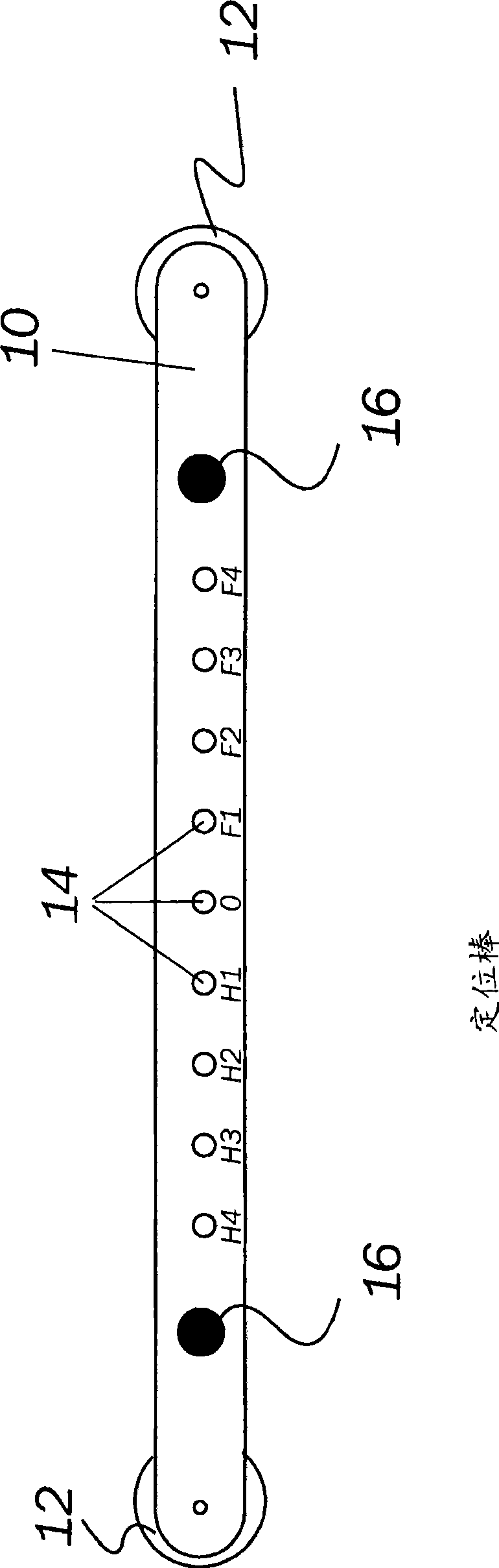
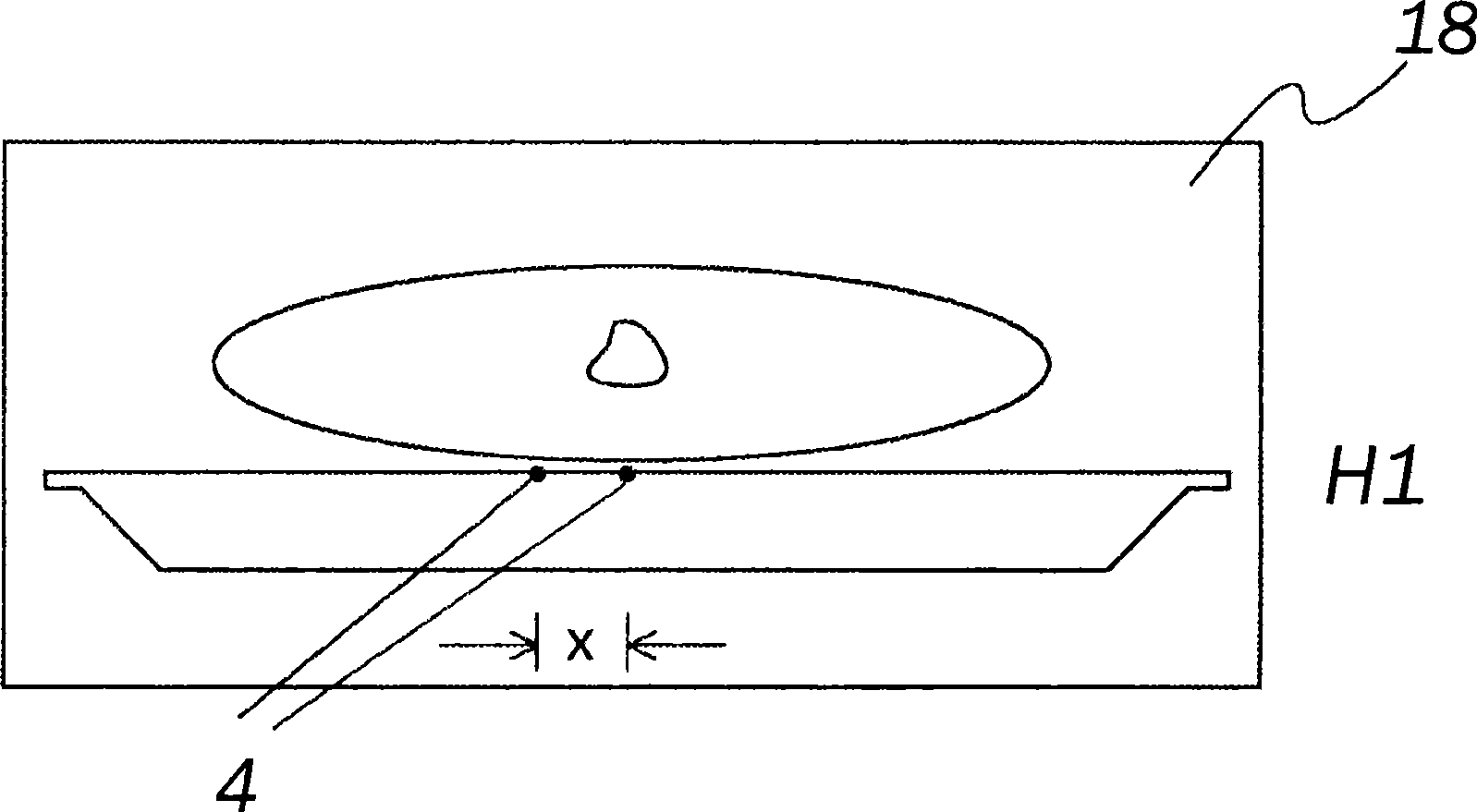
[0023] The inclusion of diagnostic imaging tools directly on the radiation therapy machine (which may be a LINAC, proton therapy or other variant) means that markers can now be used to identify the location of patient positioning devices and table tops. Continuous markers in the form of paired branch lines have been used for many years to provide axial position on the CT scanner. However, this method does not allow the user to pinpoint a specific location. Physical patient positionin...


PUM


Abstract

The present invention provides a patient couch top or device for quickly and accurately positioning a patient during simulation and treatment by placing a series of small fiducial markers in discrete locations on the couch top or device. With use of the fiducial markers, the present invention allows for the correction for misalignment and deformation of patient positioning equipment which occurs due in part to a patient's size and weight. The present invention also provides a method for positioning a patient and correcting for deformation of the couch top or device.

Description

Background of the invention [0001] This application claims priority to and benefit of US Provisional Application 60 / 795,836, filed April 27, 2006, entitled "Radiation Therapy Patient Couch Top Compatible with Diagnostic Imaging." [0002] The state of the art in cancer radiation therapy is increasingly based on the pinpoint application of high-energy radiation, which is adjusted with high precision to the shape and location of the cancer tumor. Modern techniques such as IMRT use a pencil-sized beam whose cross-sectional shape matches the tumor. This allows doctors to increase the therapeutic dose to the cancer target without harming surrounding healthy tissue. As the size of therapeutic beams decreases, precise positioning of the beam becomes critical. If the highly tuned beam is a few millimeters off target, it can miss the tumor completely. [0003] Thanks to these new technologies, there is an increasing desire to know exactly the location and shape of the tumor while th...

Claims


Application Information

Patent Timeline
Patent Type & Authority Applications(China)
IPC IPC(8): A61B5/05
CPCA61N2005/1061A61B6/08A61B6/0492A61N5/1049A61B6/04A61B5/05
Inventor D·D·科彭斯
Owner QFIX SYSTEM LLC
Why Eureka
Try Eureka