Compact spinning apparatus for spinning frame

A spinning frame, compact technology, applied in the direction of spinning machines, textiles, papermaking, drafting equipment, etc., can solve the problems that the yarn quality in the twisting triangle area cannot be eliminated, the speed of the compact spinning device is not synchronized, and the structure is complicated.

Inactive Publication Date: 2011-02-09
绍兴华裕纺机有限公司
View PDF2 Cites 0 Cited by
  • Summary
  • Abstract
  • Description
  • Claims
  • Application Information

AI Technical Summary

Problems solved by technology

For example, a compact spinning device with patent No. 03228410.1 is provided with an air suction pipe with two ends fixed on two adjacent roller seats with air suction port and exhaust port, which is set outside the air suction pipe and corresponds to the position of the air suction port. The cohesive sleeve with a condensation groove in the circumferential direction of the cohesive sleeve, the tension device stuck in the cohesive sleeve, the air-permeable conveying ring and the transmission pressure device set on the cohesive sleeve, the compact spinning device can make the fiber bundle output by the front roller Under the action of negative pressure generated by the exhaust system, it is adsorbed on the air-permeable conveying ring, and under the action of the pressurized transmission device and the air-permeable conveying ring, the fiber bundle is tightened and straightened to achieve twisting into yarn. The yarn device can better solve the original "hairiness" problem and improve the yarn quality, but there are also some shortcomings, such as complex structure and high production cost; and the compact spinning device and the roller are driven by different power devices. It is easy to cause the speed of the compact spinning device to be out of sync with the speed of the rollers, resulting in yarn blocking and yarn breakage, which cannot eliminate the twisting triangle and affect the quality of the yarn

Method used


Image

  • Compact spinning apparatus for spinning frame
  • Compact spinning apparatus for spinning frame

Examples


Embodiment Construction

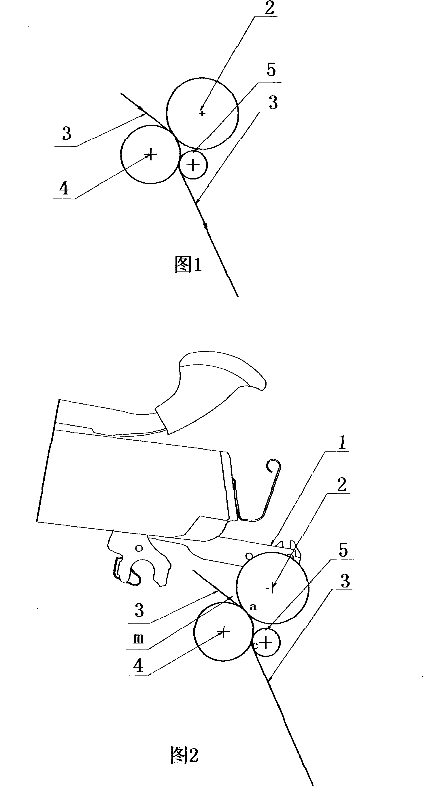
[0014] Such as figure 1 , figure 2 As shown, the front top roller 2 is installed on the cradle 1 of the spinning frame, and the front roller 4 is installed under the cradle 1 and pressed against the front top roller 2, and is formed between the front roller 4 and the front top roller 2. The contact area a of the pre-drafting device constitutes the drafting area m between the output end a of the drafting pressure roller composed of the front roller 4 and the front top roller 2; Pressing on the front roller 4, a contact area c is formed between the converging roller 5 and the bottom roller 4.

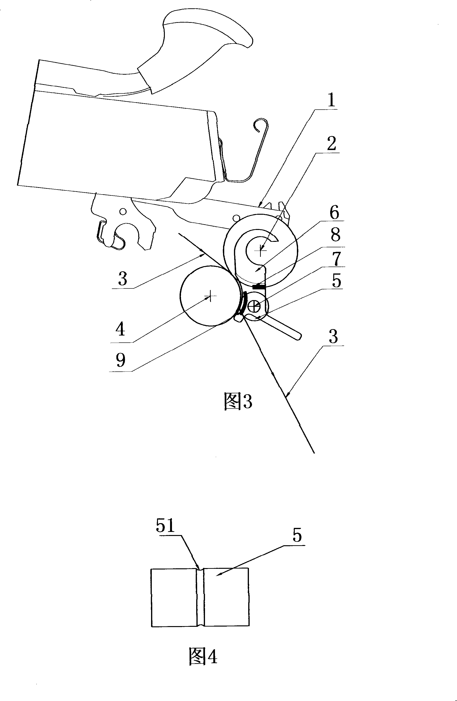
[0015] combine Figure 4 As shown, on the circumferential surface of the converging roller 5, there are several converging grooves 51 that are funnel-shaped from wide to narrow facing the direction of arrival of the yarn 3, so as to facilitate the converging of the yarn 3, and the converging roller 5 can pass through gravity and mechanical prestress. Or the magnetic attraction is pres...


PUM


Abstract

The invention relates to a compact spinning device of a spinning machine, belonging to the technical field of textile machinery. A front leather roller is arranged at the cradle of the spinning machine, a front roller is arranged below the cradle and is pressed on the front leather roller, and a contacting area a is formed between the front roller and the front leather roller. The characteristicsof the invention lie in that: a bunching roller is arranged below the front leather roller, is pressed on the front roller and moves synchronously with the front roller, a contacting area c is formedbetween the bunching roller and a lower roller, and a plurality of bunching groove paths which face the coming direction of the yarns and are in a shape of funnel are opened at the periphery of the bunching roller. The invention has a simple structure and excellent bunching effect, and produces uniform yarn strips after twisting.

Description

technical field [0001] The invention relates to a textile machine, in particular to a compact spinning device of a spinning frame. Background technique [0002] In the spinning process of the traditional spinning frame, after the drafted sliver leaves the front roller with a certain width and in a free state, it is immediately processed into a yarn, and a spun yarn is formed in the yarn forming area In the triangular area, because the loose fibers in the spinning triangular area cannot be well controlled, many fiber whiskers around the yarn sliver will be scattered in advance and cannot be bundled, and the scattered fibers will protrude out of the yarn because they cannot be squeezed into the yarn The "hairiness" that occurs in spinning is formed, which seriously affects the yarn quality and reduces the fiber utilization. Therefore, it is necessary to improve the conveying form of the sliver before twisting, even if the sliver is parallel, straight and closely arranged. At...

Claims


Application Information

Patent Timeline
Patent Type & Authority Patents(China)
IPC IPC(8): D01H5/72
Inventor 刘光容
Owner 绍兴华裕纺机有限公司
Why Eureka
Try Eureka